I’d bet you those companies have to pay some sort of fee to System Sensor in order to use their technology. Just because other companies use it doesn’t mean it’s handed out for free. ![]() It’s definitely cheaper for those companies to license System Sensor’s technology than to develop their own, which is probably mainly why they do it.
It’s definitely cheaper for those companies to license System Sensor’s technology than to develop their own, which is probably mainly why they do it.
I’ll guarantee you that they’re not going to give a kid with no lawyers or company behind them the rights to use their proprietary addressable protocol. They don’t just give this stuff away like candy…
2 Likes
No Comment
…then why bother posting? :lol:
Thanks everyone yes is do have a addressable panel and was just wondering
Can someone explain how the SLC powers devices? I do understand the serial(?) system for data, just not how the heck it powers it…
Are the systemsensor SD355(A)/SD355T(A) compatible to use on notifier and fire-light panels ?
mind = blown
I can only answer that for Mapnet, but the others are probably somewhat similar. If someone has looked at some other brands with a scope they can fill in that information.
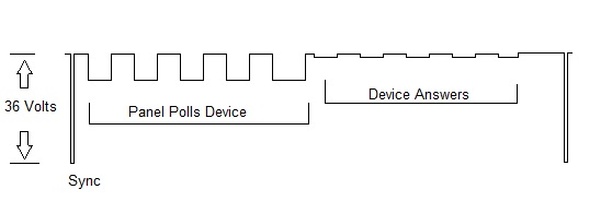
The drawing below represents a Mapnet poll and answer of one device. The channel is powered by 36 volts DC. A poll begins with a sync pulse which is only a few milliseconds… Then the Mapnet card polls the device address. That data is only around 10 volts. The device responds by switching a resistor on and off which is sensed in the Mapnet card. So 99.99% of the time the devices have between 26 to 36 volts power available. Capacitors in the devices smooth out the variations in voltage to power the internal circuit.
Is MapNet an older protocol? I would love to make a addressable demo board.
MAPNET was replaced by MAPNET II in the 90s and then that was replaced by IDNET in the very late 90s, with the 4010.
System Sensor’s “CLIP” protocol and its newer high speed versions work off this same principle of alternating the power and the data. If you put a multimeter on an SLC loop it is possible to read both DC and AC voltage. The SLC loop specifications say that it puts out 30 to 32 VDC and about 10 VAC. I normally get 15 VDC and 10 VAC on a loop when I put my meter on it. The reason for only getting half is because of the alternation that it does.
I wish I had an oscilloscope that I could hook up to it to see exactly what is happening here though.
1 Like
The 10 volt data for the card polling the devices is Mapnet II. Mapnet I used about half of that level. The change from type I to type II was a hardware improvement. The data level was increased and there were changes to the receive circuit in the field devices. That happened during 2120 CDT times. Mapnet I was long gone when 4100 came out. The type I devices are compatible with type II panel hardware. I replaced several early addressable 2120 systems using Mapnet I field devices with 4100 network systems.
1 Like
Same thought here with the scope. You can do just about anything on those.
Ok, that makes sense.
So how does polling work? like how does the device report everything?
I explained how SLC devices are powered on a Mapnet circuit. IDnet works about the same but passes more data.
I am not sure how to answer this question. I know generally how this works. However, if you are looking for a byte by byte and bit by bit communication analysis, that is information I never had.
OK. I was just seeing if you could explain it better. I guess I need to aquire a panel, devices, and a scope.
I thought my first post covered this fairly well.
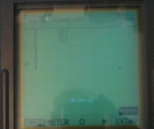
However, if you want a scope photo here is one. The phone camera has to get too close for a clear image. I need to find the charger for my good camera. Notice the device reply is not visible. The reply is current activated so does not change the SLC voltage much at all. In my drawing I exaggerated the level for clarity. In practice the reply is only visible on a scope when the trace is greatly expanded vertically.
Sorry, Addressable is just confusing to me. It’s making more sense…
What scope where you using?
That is a Fluke 91 Scopemeter I bought second hand years ago.
It’s interesting how the addressable protocols work.
I’ve designed a schematic for my own SLC protocol that uses Simplex’s implementation but has some modifications. I’ve yet to design the circuit that checks the SLC for shorts, ground faults, etc… But I’m not really worried about that as of yet since I haven’t even build the concept circuit to see if it even works. I’ve also got to design the actual talking protocol for communication over the wire.
I’m using FlashScan as a comparison for now and if my idea works, it’ll blow it out of the water (that is, if I decide about building the circuit and test it).
1 Like
do the monitor modules have id’s that are linked to the brand eg fire-light, notifier
1 Like
Short answer: Yes
Longer answer: Depends
Other than those it must be used on the companys brand panel.
1 Like