Hello everyone,
I’ve been meaning to make this post for a long time, I’m gonna directly put it out there: I came into possession, thanks to a fellow collector, of a nigh obscure, in fact, so obscure that the only acknowledgement of its existence is a document from Eaton about detector replacement and a couple of posts in a private FB group.
This panel, or should I say, these panels (as there is a first, and even more obscure version, even though the differences aren’t significant enough to justify making its own post) are certainly not getting any easier to find, to give you a rough idea, they’re about as easy to find as a FCI 7200, speaking of which, @HappyJigg’s topic on the 7200 is what inspired me to make this one.
I’m not gonna focus on the history of its lineup, as I have no clue where to even start to be honest, I just know my version of that panel is from the era where Nugelec got taken over by Cooper (yes, that same Cooper that took over Wheelock), I just know there is the first version which was introduced around the late 1990’s (circa 1997) and discontinued in 2003.
So, I’m writing this just so it doesn’t totally fade into obscurity, and in the very unlikely event that another collector comes upon one of these, and a couple of notes that may or may not be useful, I’m not trying to be as exhaustive as possible and most of this is largely checked against the manual when possible or applicable.
Without further ado, here that panel, the Nugelec PAJ31100 (as you’ll see, there’s multiple sub-models I’ll explain a couple of lines further down) Tableau de Signalisation Paramétrable (I’ll call it TSP from this point onward for brevity)
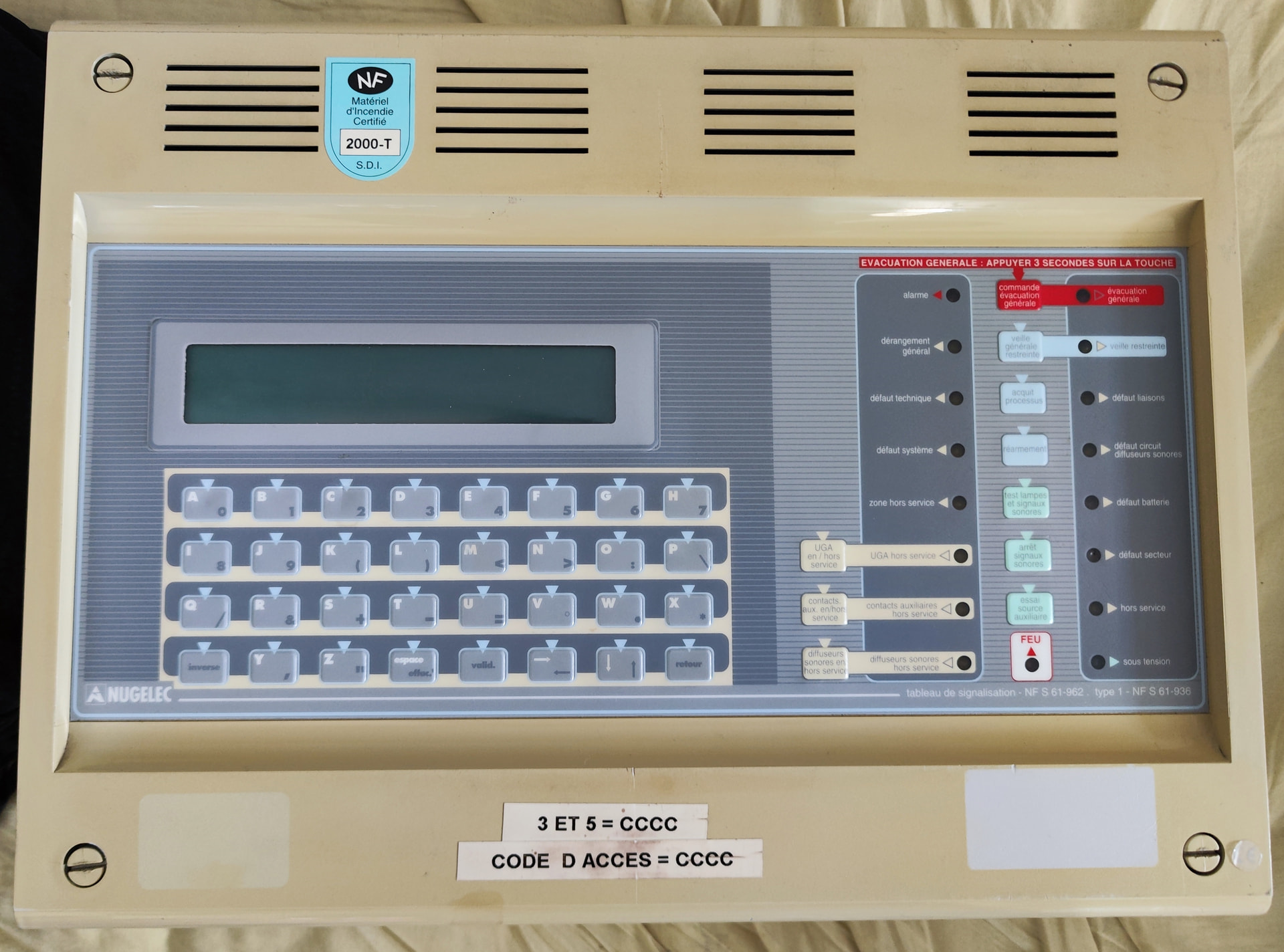
(apologies for the pictures with it powered off, forgot to plug it in when I took these pictures)
On the front, it looks like most Nugelec panels of that era, but as you can immediately see, there are two things that jump out, the fact it has a whole array of keys, and a long LCD dot matrix display.
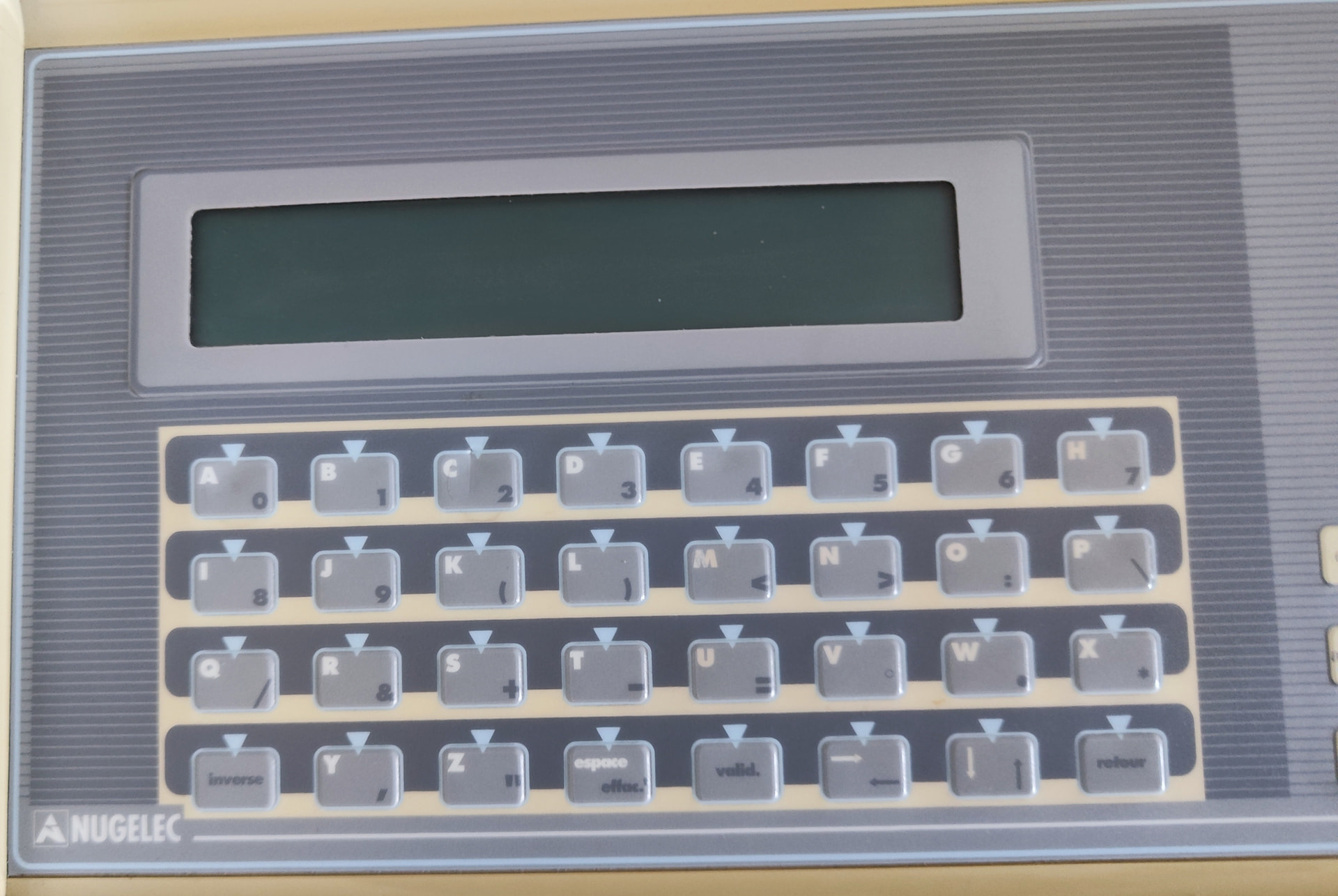
This is where you navigate through menus (and there’s a ton), the keyboard (keypad?) has two character sets, letters (main) and numbers/symbols (alternate), switching between the two sets is rather clunky as you have to hold the “INVERSE” key AND the corresponding symbol key you want to press.
For example, if you are in the zone programming menu and want to change a point’s label, to, I don’t know, something random, like, “ZDM01”, you’d press Z, D, M, Inverse+A (0), Inverse+B (1), I think you can see how clunky it feels (plus Nugelec panels of that era quickly earned a reputation of having buttons that often don’t register presses well).
When the panel is idle without any troubles, it displays something akin to this:

(image taken from the manual, which was given to me by a fellow collector who gave me the panel)
Let’s annotate it for clarity, shall we? (don’t mind the quick and dirty MSPaint tomfoolery)

There are three counters that appear all the time, the first one (FEU) is the number of points with an active fire condition, the second (DRG) tallies any and all troubles (i.e, missing point, open trouble on a line, battery trouble and so on), while the third one (HS) tallies disabled devices (points) or lines.
The fourth one is actually nifty, if you program the panel to make delay the activation of the UGA (Unité de Gestion d’Alarme) sounder circuit (basically a NAC), it will show a countdown, but if you manually activate the NAC WHILE the panel is in alarm (using the “Évacuation générale” button) it will still count down. In certain cases it changes to something else.
When the panel registers a fire condition on a point, this quickly changes, the FEU counter is incremented, and the screen will show something like this (again, pulled from the manual):
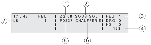
- Detection zone (oddly enough, the manual calls it a “zone géographique” but on mine, it shows as “ZD” and “zone détection assignée”)
- Label of the zone (in this screenshot it’s written “basement”)
- Fire alarm counter
- Time before the UGA activates the sounder circuit (if a delay is set)
- Point in alarm
- Name of the point in alarm (labeled here as a point located in a boiler/mechanical room)
- Line where the point in alarm is located
For troubles it’s sensibly similar (and the manual this time points out the time where the event happened):
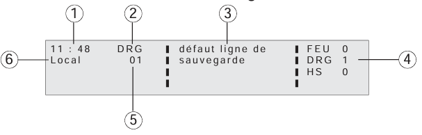
- Time where the trouble (or fire alarm in case of a fire condition) appeared
- Type of event (in this case, trouble)
- Name of the trouble event
- Trouble counter
- Order where the trouble event has happened
- Type of trouble (in this case, local, which means it’s an internal panel trouble)
That’s about it for the display, I’ll eventually come back to it later on another post in this topic (and move this section there when that’s done).
Now if we move to the right hand side of the panel…
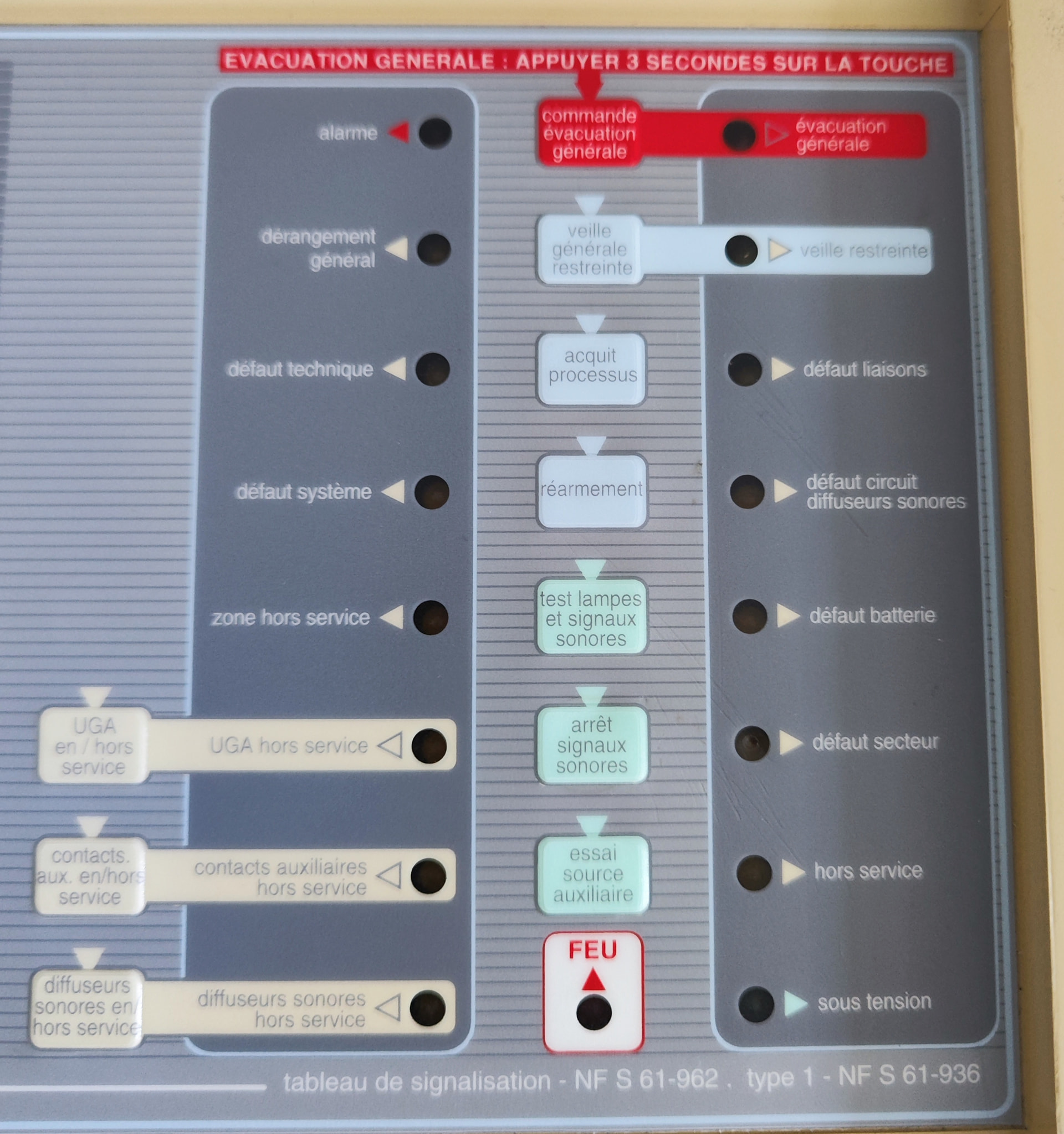
Now it looks more classic, there’s your usual indicators, AC power on (sous tension), system out of order (French fire alarm panels are required to have a tertiary power source which is just used to continuously sound the piezo off and light up a “système hors service” indicator, to indicate that the system is no longer functional)..
I’ll first describe the left column’s indicators, starting from the bottom:
- Diffuseurs sonores hors service (sounders disabled), lights up when the sounders are disabled in the Level 3 menu
- Contacts auxiliaires hors service (auxiliary report contacts disabled), same as above but when you press “contact aux en/hors service” it’ll light up, although on my panel the LED appears to be burnt out.
- UGA hors service same thing, except this lights up when the UGA is fully disabled wholesale. Equivalent to “NAC disabled” troubles on some panels.
- Zone hors service (Zone disabled), lights up when a detection zone is disabled.
- Défaut système, (system trouble), lights up when a general system trouble occurs, such as when the panel initially boots up and you don’t initialize the cards.
- Défaut technique (technical trouble), TSP panels can also do technical monitoring (things like monitoring trouble relays on elevators, ventilation systems and HVAC systems) if you have the correct modules.
- Dérangement général (general trouble) lights up when a trouble is active (IIRC)
- Alarme (fire alarm) lights up when a alarm condition is raised.
Middle column only has buttons and the lone “FEU” (Fire) indicator:
- Essai source auxiliaire (aux source test) lights up the “système hors service” indicator and continuously sounds off the buzzer as long as this button is held down.
- Arrêt signal sonore (tone silence/acknowledge), quite obvious, silences the buzzer when pressed, also amusingly on this panel, when you press a button it makes a small beep, so if you hold down the ACK button it makes a series of beeps (beep beep beep beep beep) at a very fast rate. I do wonder if it’s intentional or just a bug in the firmware?
- Test lampes et signaux sonores (light/buzzer test), when pressed, the buzzer goes off steadily and all the indicators light up. You can also do the “hold down rapid-fire beep” trick with this button and it does so even faster.
- Acquittement Processus (process acknowledge), when the panel is in alarm and the UGA has a delay programmed, you can hit this button to cancel the countdown. Won’t work if you manually activate the sounders using the “commande évacuation générale” button or the UGA is set to instantly activate the sounders.
- Veille générale/restreinte (restricted surveillance? I’m not too sure how to translate that one…), this is used to inhibit the UGA’s automatic activation while retaining the possibility to manually set off the sounders, this is to be used when there is a manual surveillance in the facility, for instance, if a fire alarm is reported to the panel while the system is in veille restreinte, instead of directly activating the sounders, it will wait for someone to go and verify the zone where the alarm was reported (this process is known as a “levée de doute” in french, could be summed up as a “physical fire confirmation”) at the end of the levée de doute, if it’s a false alarm, the operator can then go and reset the system (after resetting the call point in the case of a call point being activated), but if there is a confirmed fire, the operator can activate the sounders manually.
- Commande évacuation générale (manual drill), manually activates the sounders, either for a fire drill or if the system is in restricted surveillance mode and has an active alarm. Above it the text says “General evacuation - hold the key for 3 seconds”
Right column:
- Sous tension (Power on), Quite obvious as to what it does, if the panel is on battery or AC power it’ll light up.
- Hors Service, Lights up when the panel’s batteries are depleted AND AC power is disconnected, in that case, the buzzer will sound off continuously (running from a small battery on the motherboard)
- Défaut secteur (Power supply trouble), lights up when panel is running on battery power
- Défaut batterie (Battery trouble), lights up when the batteries are missing or defective
- Défaut circuit diffuseurs sonores (NAC/Sounder circuit trouble) lights up when the sounder line (terminated by a 3.9kOhm resistor) is open, shorted or when the fuse is blown (amusingly enough the panel has a separate trouble for the fuse)
- Défaut liaisons (wiring trouble…? Sort of), I’m not exactly sure when it’s supposed to light up but if the panel is configured for a CMSI (Centralisateur de Mise en Sécurité Incendie, basically a secondary panel that handles anything like fire doors and smoke venting to keep it simple) or a remote annunciator, if neither is present while their lines are programmed to be enabled, this will light up
- Veille restreinte (restricted surveillance (?), supervision?) lights up when “Veille générale/restreinte” is pressed when in Level 2
- Évacuation générale (general evacuation), lights up when the sounder circuit/NAC is activated, be it manually or automatically. Additionally, when there is a sounder circuit trouble, this LED will flash, but otherwise will light up steadily.
Sorry for the gigantic wall of text, to break that a bit, I’ll focus now on the hardware side of things… If you pry off the top cover you get… this:

This is the ENTIRE front board with all the buttons I’m aware it has one of those NiCd/NiMH barrel batteries on it… an unfortunate silent killer for these panels… Mine thankfully isn’t too bad (it’s an NiMH) but it’s DEFINITELY slated for replacement, if I can find a holder that is. There is also one of those annoying (but at least when they go bad they don’t take out the whole PCB with them) potted battery Timekeeper chips, as my panel is from between 1999-2000, this chip is, of course, depleted, so every time I start my panel it resumes the clock from when it was last set.
Not shown underneath the board is… quite literally nothing aside than two headers for the power supply and the backplane bus connector.
The front board has a row of terminals:
- “Horo-contact”, this one when closed (dry contact) will cause the sounders (if compatible) to sound in a continuous tone, this relies on reversing the polarity of the sounder circuit (this has been a mainstay of Nugelec panels and sounders alike, I think Aviss Sécurité also does, at least on their Agema II panel) to use as a time signal. Doesn’t work with all sounders though.
- “Ligne de sauvegarde”, to be honest I have no idea what this one does, other than the panel excepts it to be terminated by a special module (which I don’t have) or a 15kOhm resistor (which I also don’t have as well, so I just strung together a 10kOhm resistor and a 3.9kOhm resistor and it seems to work fine?)
- Communication GTC/GTB: Normally for a central building management unit, it’s basically a serial port, also used for external programming.
- Asservissement général technique : DPST relay that closes/opens when a technical alarm is registered by the panel
- Asservissement général defaut, same as above but for trouble
- Asservissement général alarme, basically an alarm relay, there are two on this panel
- Ligne diffuseur sonores (sounder circuit), that’s where you connect the sounders, line must be terminated by a 3.9kOhm resistor.
Flipping the board up reveals the backplane and the power supply:
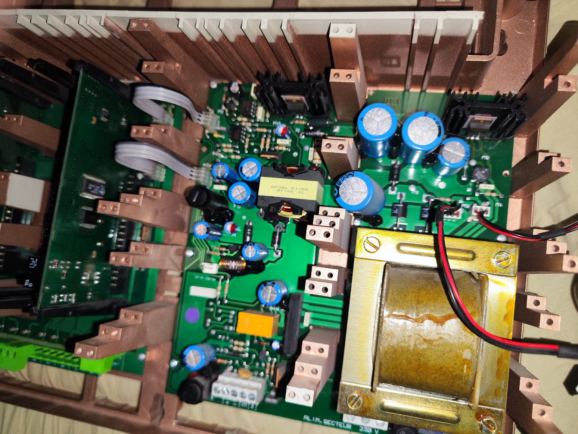
The PSU isn’t anything to write home about, it’s about as plain as it gets, a linear transformer with a rectifier and DC/DC regulator on it
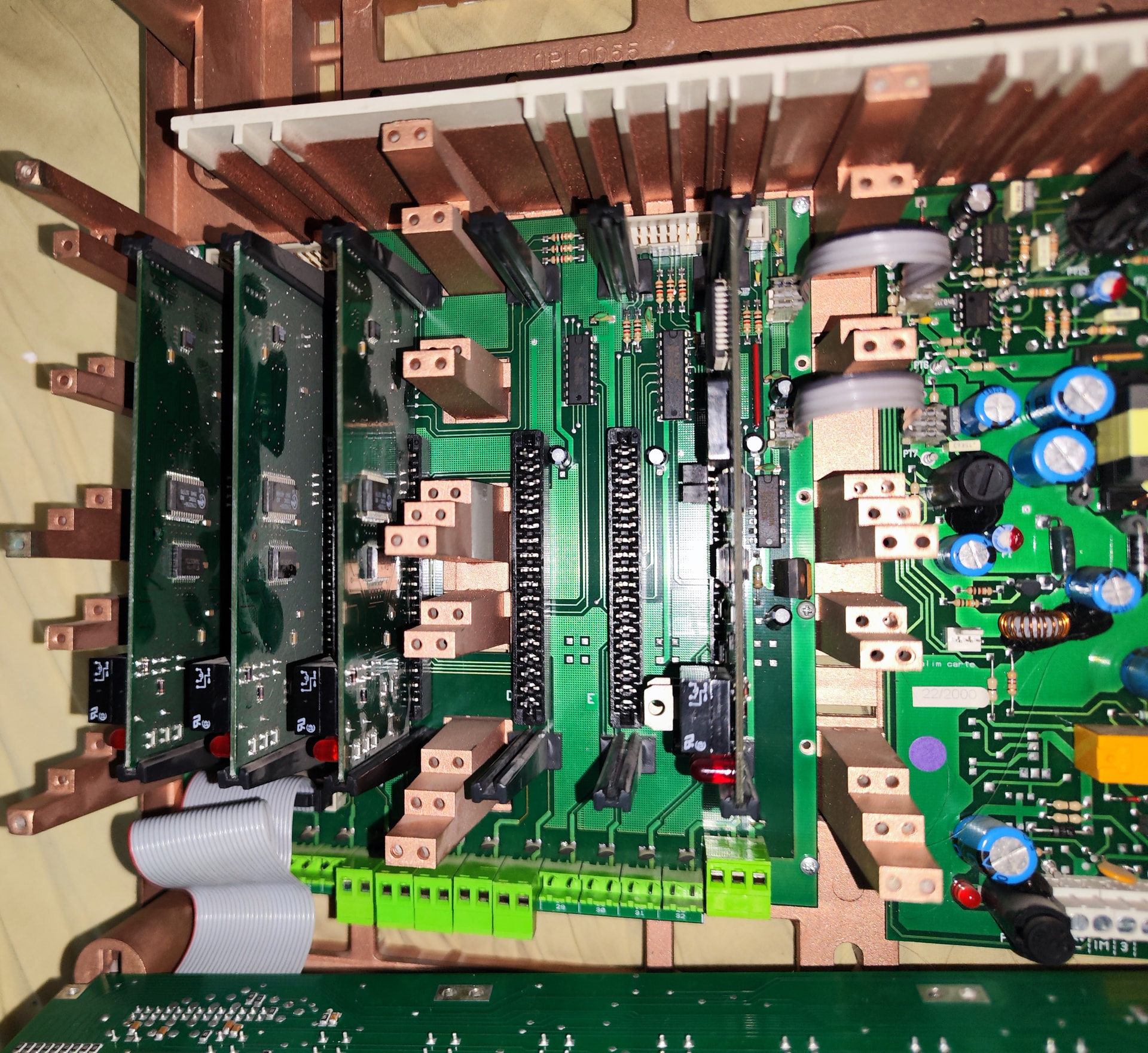
The backplane is where the magic happens, on my panel (single cabinet) there are 6 slots, slot 6 is where the CMSI/REP card (it’s actually a SLC card but with a jumper to configure it as a communication card sits (and as you can see on this picture it has two jumpers, but I’ve since fixed that, it is supposed to have one on the middle two pins), in the other slots, sit the SLC cards, each handling 3 lines with 32 points* max on each line (so this roughly gives us 96 points per card). Each card has three two-pin terminals dedicated to it (with the notable exception of the CMSI/REP card which has a 3 pin header for the annunciators, +24/-24V and serial comm.
And this is where things take a turn for the absolutely confusing. Remember when I said HappyJigg’s FCI 7200 thread inspired me to make this? Well…
…As it turns out, Nugelec literally PLASTERED Intel MCS-51 Microcontrollers wherever they could! (and unlike the FCI 7200, the Nugelec TSP is fairly snappy and responsive! If the buttons accept to cooperate that is.) From the panel itself (the front board has a 80C32, which is the ROMless variant of the 80C31, makes sense since there’s an UVEPROM near), to the devices (I have two adressable call points for this panel and they have a small card glued on the back with, you guessed it, a 80C31) and the annunciators (!) it’s MCS-51 land in here! Hell, even the SLC/CMSI-REP cards have a 80C31 on 'em!
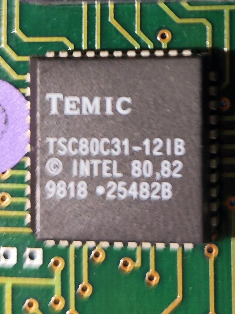
(above, 80C31 from a SLC card)
So if we count… in the panel itself there is 5 80c31/80c32 MCUs alone!
And let’s not speak about the two-cabinet (3 backplanes) or three-cabinet versions (5 backplanes) when all the SLC card slots are occupied… that would be another level of insanity.
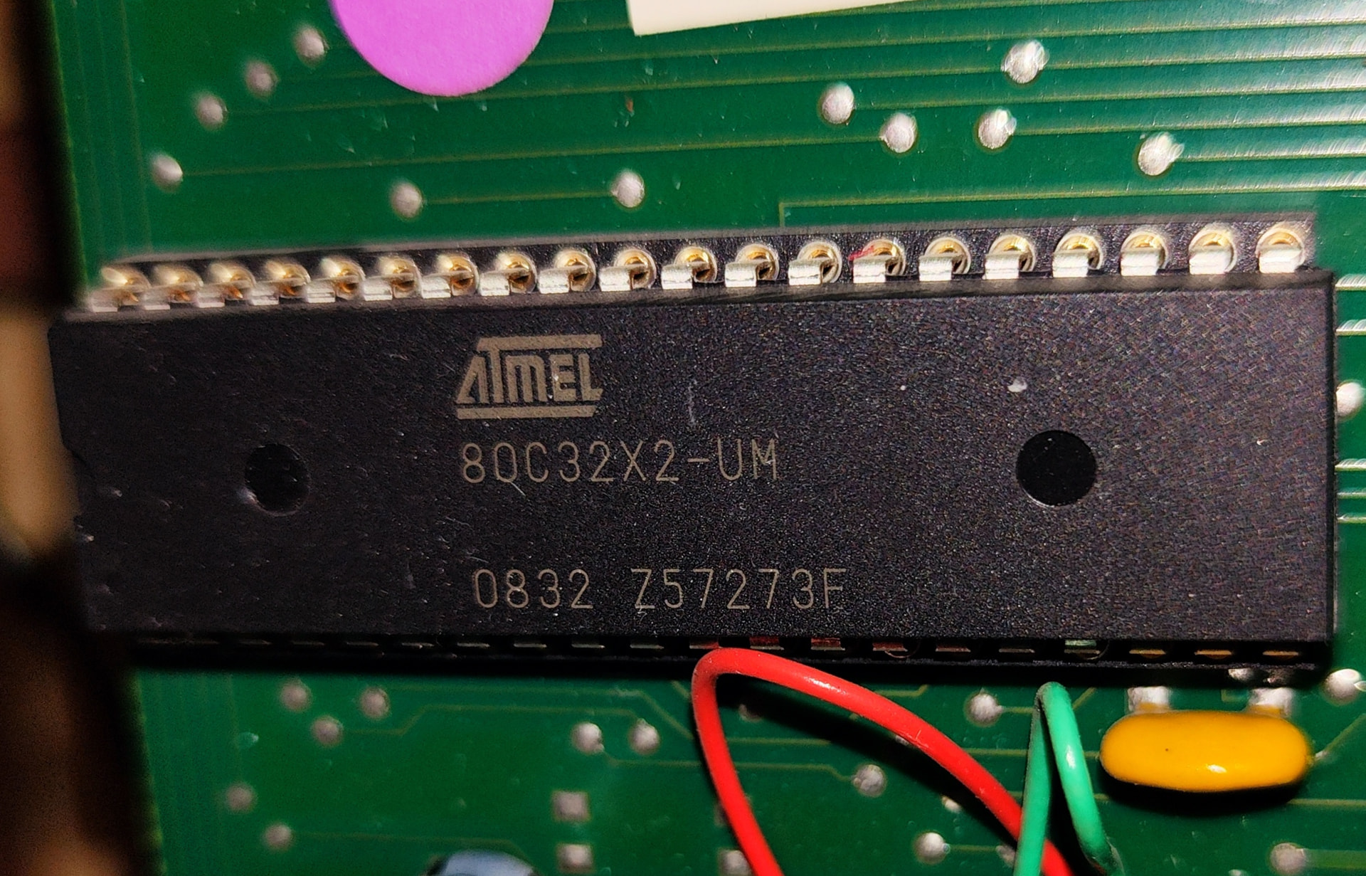
(the main board’s micocontroller, it’s date code is 2008 if I’m not mistaken..
That’s it for now, on the next post, I’ll focus on the devices for this panel, and the different sub-models for it… Trust me, there is a LOT to write about it. For now I’m done (it’s 11PM here as I’m writing this)
Cheers,
Alexis