Fire-Lite MS-2 Questions

So, long story short, my Simplex 4004 broke the other day when it started displaying non-existent troubles after powering it down. After failed attempts to clear the troubles, I realized something probably internally fried the board pretty bad (possibly the Wheelock 712-24? Guess what I’m never wiring up to a panel again?). So, I just put it on eBay for parts. Hopefully I can make $20 on it.

Luckily, though, I was able to quickly come across a replacement, a Fire-Lite MS-2. Personally, I have always hated Fire-Lite and similar brand panels (no offence to Fire-Lite fans or the company, it’s just an opinion) for a couple reasons. I just couldn’t pass this one up because of the fact it was only $75, though, and I figured it could be temporary until I can get another Simplex panel. I won the auction this afternoon and it’s already on it’s way. I have a few questions about it, though, since I have never worked with a non-Simplex panel. Just FYI, I have already read several documents and diagrams on the MS-2.

First of all, how does the grounding work? The pictures of the actual unit show no wire already going into the Earth terminal on the panel, and I don’t know how to properly ground it.

Second of all, I don’t yet have the proper resistors for it. Is it safe to temporarily power up and test with devices without resistors? Also, do I need resistors across the relay terminals, in addition to the zones and NAC?

Finally, my most important question is what alarms can I even use on it? One of the reasons I hate these panels so much is because they put out FWR, which I know can fry certain devices. What kinds of alarms should I avoid using on it? I think TrueAlerts can’t be used on it? Are electro-mechanical Simplex horns safe to use (4051, 2901-9806, 2901-9838). Can I use Simplex strobes, and do incandescent lights work on these panels? I know System Sensor, Wheelock, and Gentex are preferred devices on these systems, but I like variation. If anyone has a list of general types and series of devices that cannot be used on the MS-2 that I could see, that would greatly be appreciated! Also, is there any kind of device I can purchase that would convert the full wave rectified into regular filtered DC?

Thanks in advance!

NOTICE: I am not sure if all the information contained within this post is accurate. I have no written sources; just what prominent members have said on this board for the past 3 years, and my own experiences of owning an MS-4. I am ready for any and all rebuttals, if they come.

Just use the ground on the power cord, unless I’m mistaken.

Yes. I’ve powered an MS-4 up without resistors, and it works fine (except for the trouble LEDs being illuminated). You do not need a resistor for the relay / supervisory terminals.

That is true.

I’m not completely sure about Simplex horns. I used a 34T on an MS-4 NAC, and it sounded horrible but worked fine. I don’t know if this will have a long-term impact on the panel, however. Maybe Andrew or Destin could intervene…

I hope one exists! If so, I’d buy it instantly.

For some reason the main page on their website for the MS-2 doesn’t link the manual… not sure if you’ve seen this or not:
http://www.firelite.com/en-US/documentation/Documents/51512.pdf

On page 19 it shows earth ground going to a mounting stud on the transformer which should ground the can.

You need resistors on all unused zones (nac’s and initiating devices) or the panel will show a trouble, but for your purposes it’s not a big deal if you power it on without a resistor. The relays are not supervised, so they don’t need resistors.

There’s a device compatibility chart on their website. Honestly you’d be better off getting a nac booster panel to power all of your signals, and never run them directly off of an facp again. might save you a panel next time!
http://www.cooperindustries.com/content/public/en/safety/notification/products/life_safety_notification/wheelock_8-amp_powersupply.html
http://www.firelite.com/en-us/Pages/Product.aspx?category=PowerSupplies&cat=HLS-FIRELITE&pid=fcps-24fs8

etc.

Alright, thanks for the help! That seems to answer some of my questions. I don’t think I’m going to go with a NAC extender right now, but I’ll defiantly be careful what I wire up. Like I said, that 712 chime was probably a bad situation waiting to happen. I polarized it and put an EMF suppression diode on it, as the guys here said, yet I think it still fried the panel. I know I’m a lot more limited to the devices I can wire up to the MS-2 anyway, so I’ll defiantly be more careful.

Keep in mind that the MS-2 only outputs 3 amps of current, so make sure that whatever devices you decide to hook up to it don’t exceed a 3 amp draw.

if you add a cpacitor to the outputs, it should give you filtered DC

Sounds simple enough, however things are never as easy as they seem.

As anyone who deals with fire alarm knows a NAC puts out supervisory voltage in opposite polarity of the alarm voltage. This adds complications to just throwing a capacitor across the NAC.

To have enough filtering effect a capacitor has to be fairly large. Where some residual ripple is not a problem, about 1,000 µF per amp of current draw will work. This requires an electrolytic capacitor. Electrolytic capacitors are polarity sensitive components and should NEVER have a reverse polarity voltage applied to them. This breaks down the electrolyte film between the plates and causes the capacitor to short out.

To use an electrolytic capacitor on a NAC, an isolating diode has to be used so that the capacitor will only have the correct polarity voltage applied. Something like this.

Notice I specified a minimum 6 amp diode. This is due to the inrush surge caused by a capacitor. A 2,700 µF capacitor can have a 6 amp charge up surge when the circuit turns on. That surge could overload the relays or transistors that activate the NAC and damage the fire alarm panel. Or at least shorten its useful life.

The latest fire alarm power supplies carry two current ratings. A “special application” current rating and a “regulated 24” current rating. The special application rating applies when signal devices that are tested and compatible with the power supply are used. The regulated 24 rating is much lower current and has to be used when devices that are not listed to be connected to the panel are used. I have seen ratings where a 9 amp rated power supply becomes a 4 amp rated power supply. Current inrush is one of the factors that prompted UL to create this rating system.

There is another way to provide filtered DC for NAC devices in a hobby system. This could not be done in a live system protecting a building because it defeats the requirement of supervision to the device terminals.

By filtering each device a smaller capacitor (maybe 100 µF or less) and lower current diode can be used. A benefit is that the EOLR can be placed at the end of the circuit to provide some supervision. The diode at each device prevents the application of reverse polarity voltage to the capacitor. Since hobby systems only use a few devices on a NAC, the total of the few capacitors will not stress the fire alarm panel components operating the NAC.

The diagram below shows this. I added the stub wiring on the positive side of each device to show how the supervision to the device terminals is defeated.

Just another thing, if the buttons are not working as soon as you press them it is because fire lite makes very unresponsive buttons so you have to hold them sometimes. One thing from personal experience is that you do want to get the proper 4.7k 1/2 watt resistors and put them into the actual panel screw terminals on the nac and 2 zones. Powering up without resistors could cause significant damage to your panel. Owning an ms 2, I have attempted to wire up the panel. It should be the following

Notification Devices:

+NAC---------------+horn/and or strobe ---- next device or eol (end of line resistors can be placed on the panel itself on the zone terminals)
-NAC---------------- -horn/strobe ----------- next device or eol

Pull stations:

  • Zone 1 IDC-------------- +Pull station ----------- next device or eol ( eol can also be put on panel)
    -Zone 1 IDC---------------- -Pull station------------ next device or eol

Smoke detectors:

+Resetable Power------------- +Smoke detector------------ eol or next smoke detector only
-Resetable Power-------------- - Smoke detector----------- eol or next smoke detector

+Zone 2 IDC------------- +Smoke detector----------eol or next device

  • Zone 2 IDC------------- - Smoke detector-----------eol or next device

Some of the information presented in the previous post and referenced in this post is incorrect. The panel wiring guides supersede anything presented in this post or the previous.

This is wired incorrectly. The horn strobe positive must go to the negative on the panel board. Unless specifically stated, NAC polarity is given in the supervisory state, meaning when the panel is sending reverse polarity voltage into the circuit.

A resistor is NOT placed on this output. Instead, an EOL relay should be used to break the zone circuit that the 4-wire smoke is connected to at loss of power to the relay, in order to provide supervision of the resetable power output.

Thanks for the help, everyone! I might try to un-polarize it with what Retired STR told me in the future. Now are the resistors going to be the same for both zones and NAC? Both my 4001 and 4004 had to have two separate types of resistors for the zones and NACs.

Yes, they’re all the same. All supervised circuits on the MS-2 use 4.7K 1/2 Watt resistors.

Here’s a link to the manual if you need it: http://www.firelite.com/CatalogDocuments/51512.pdf

I see, thank you. Looks like I’ll be good to go.

I just re-read what kcin556 wrote. So, to verify, I wire the alarm into the NAC backwards?

Some panels show the polarity in the alarm condition, others show it in the supervisory condition. On my SXL-EX panel, it is shown in the supervisory condition, so the wires are backwards. You need to check your panel’s documentation to find whether the polarity is shown in the alarm or supervisory condition.

If it is shown in alarm condition: wire the positive NAC terminal to positive device terminal as normal.
If it is shown in the supervisory condition: wire the positive NAC terminal to the negative device terminal.

I think the MS-2 may be shown in alarm just to make things simple, but make sure that holds true to what is printed on the PCB.

I understand the diagrams are different, but is the polarity on the PCB always the alarm condition?

I can’t really say yes or no on this, because none of my panels have polarity markings printed on the boards. Some panels have markings on the PCB such as “B+” and “B-” or simply + and - marks.

Here’s one of my panels for example:

Wiring diagram for the NAC’s, notice it is shown in supervisory.

The wires do correspond to positive/negative on the devices, demonstrating how the polarity of the wiring must be flipped in this case.

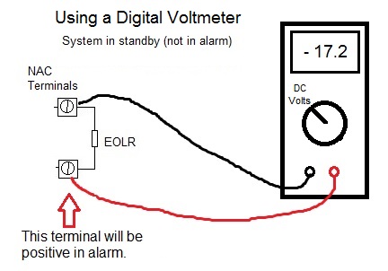
A digital voltmeter makes determining the polarity to connect really easy. A DC NAC reverses polarity between standby supervisory condition and alarm condition. Connect a digital voltmeter to the terminals so that the meter shows a negative voltage. The terminal with the RED test probe connected will go to positive in alarm.

Alright, thanks!

Firelite terminals are shown in standby state. You asked about incadesents. You can not mix them on this panel. The nac circuits for inc. Lamps and chimes will have to be set as temporal and a newer horn strobe must be set as constant.