These are questions from a beginner.
This is a location where there are people 24 hours a day, and the ceiling is finished with gypsum boards, so it’s frustrating that it’s not easy to access the ceiling.
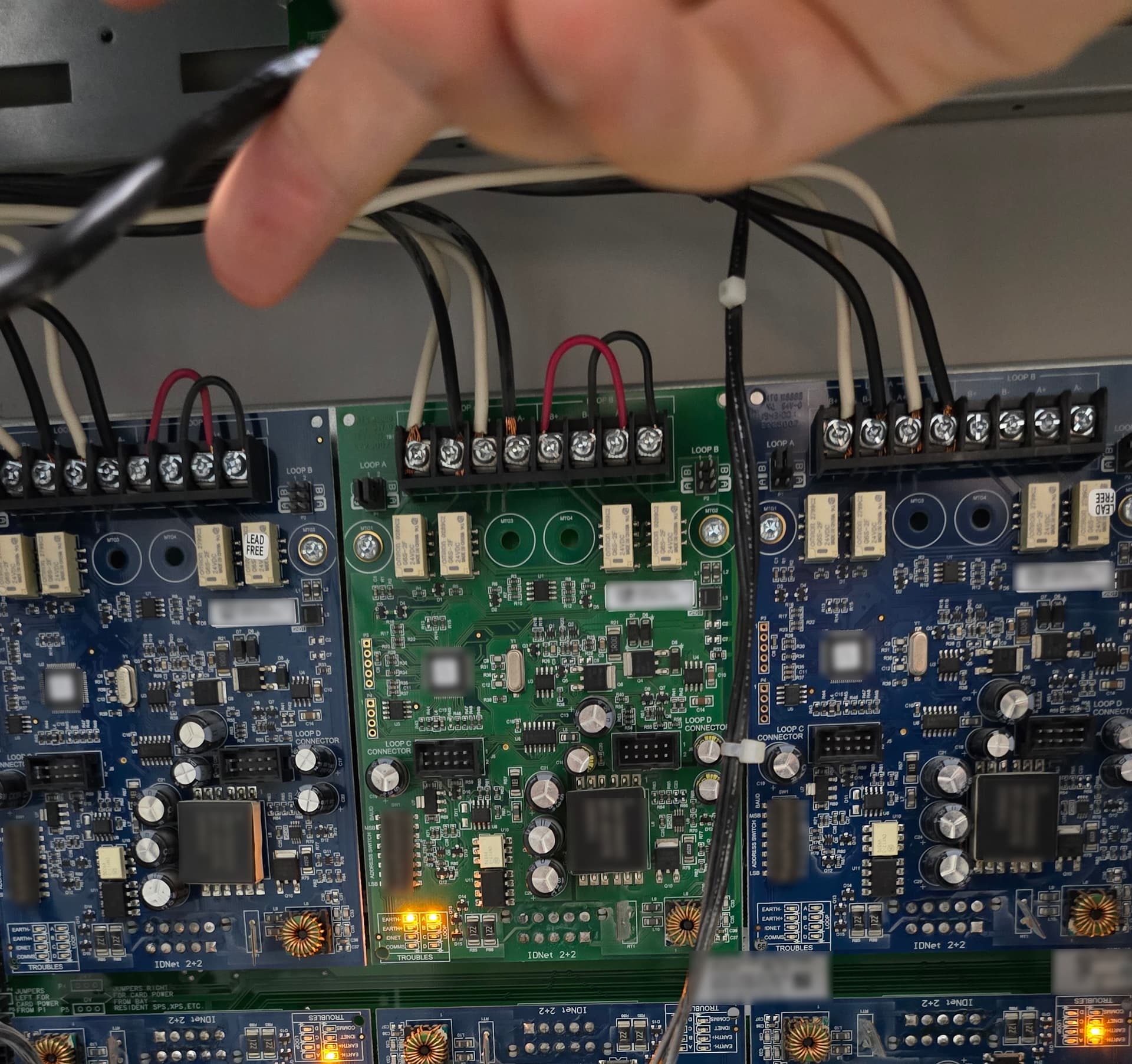
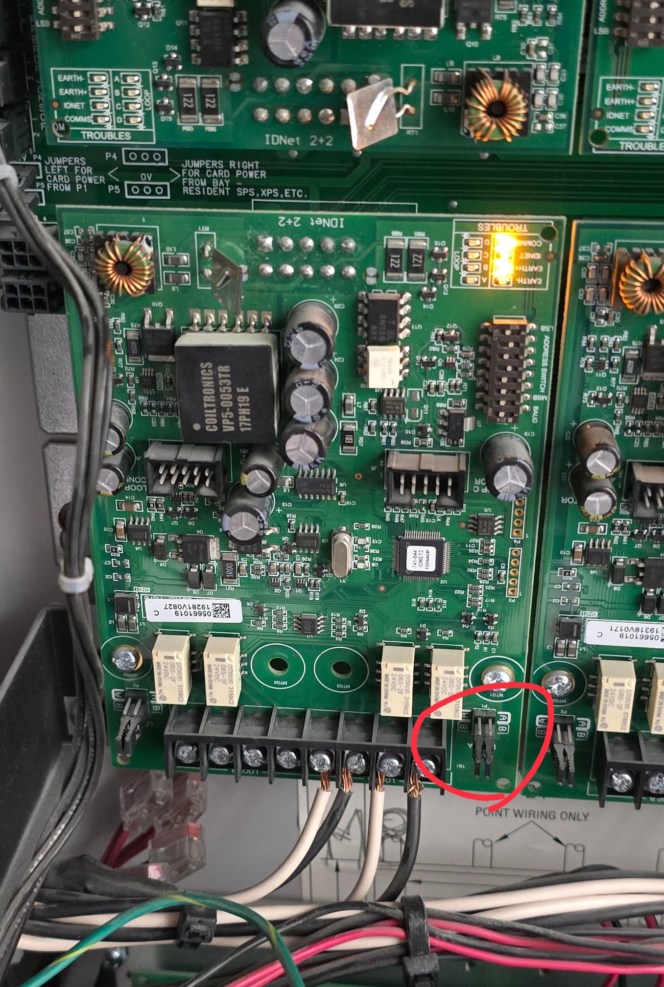
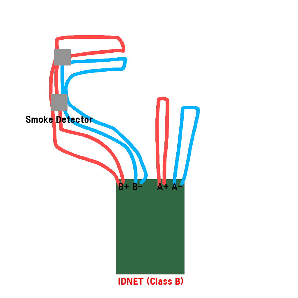
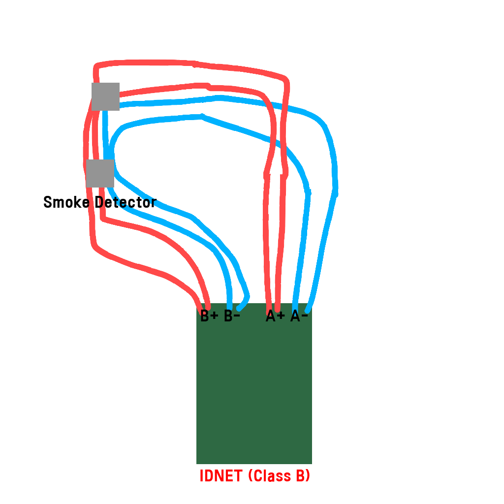
1.This is an IDNet2 module. It seems like this wiring is configured as Class A, is that correct?
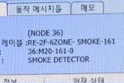
2.On the graphic display, the point name is shown as 38:M4-8-0.
We have multiple 4100ES FACPs in our building, labeled as 38, 39, and so on. M4 is the address of the 4090-9118 relay module installed inside the indoor fire hydrant. 8 is the address of the detector.
What I’m curious about is whether the detector is also grouped with that relay under IDNet? Or are the detectors only grouped under the IDNet card? Considering a detector short circuit, it seems like it wouldn’t be appropriate for the relay to be grouped with it.
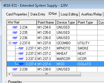
3.Occasionally, detector wiring runs to the upper floors. In that case, should the first device connected on the upper floor be an isolator detector? It seems like that would prevent a short circuit.
4.Is it possible for the FACP to detect the detectors connected to the loop on the IDNet2 card? If so, I’d like to know how.
You can tell if it’s class A with the jumpers on the exterior sides of the connectors jumpers on A mean class a and on B class B.
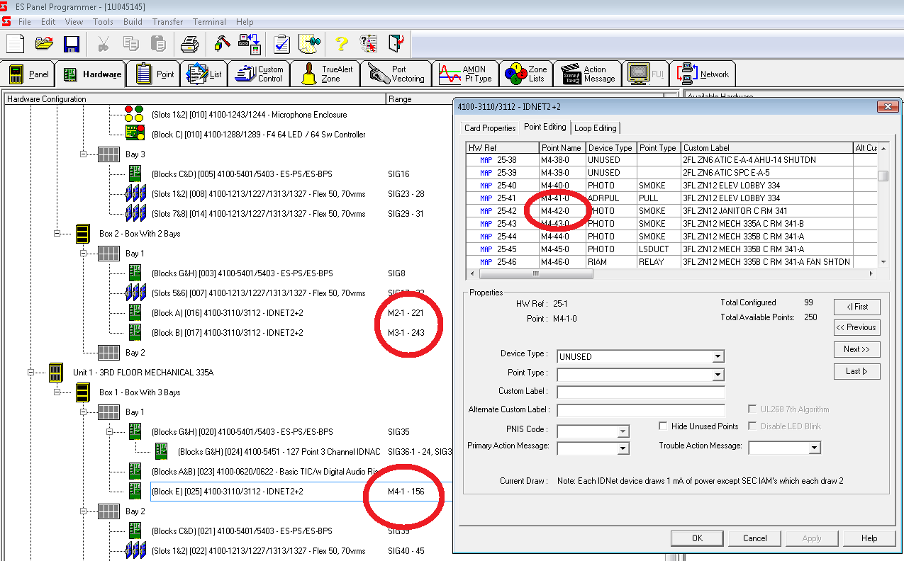
M4 is the idnet card, most likely the forth card in this node, -8 is the device and -0 is for special functions such as if it’s a combo detector -1 would be smoke and -2 heat(-0 and -3 are for other purposes on combos)
Isolators isolate a short circuit, depending on the application it might not be necessary but obviously would make troubleshooting easier.
it will only properly identify detectors that it is aware of through programming, otherwise it will show idnet extra device.
Regarding question 2, at first, I also thought it was the IDNet card slot number.
However, as you can see, there is a number ‘M20,’ and today I will remove the IDNet cable connected to the corresponding relay to check if the connected detector stops working.
As for question 4, I was asking if there is a search function in the 4100ES. Can we view the list of detectors connected to the IDNet card in slot 3?
Thank you for your response.
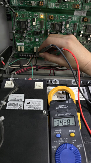
I inspected terminal 42 on the M5 IDNET card of the 4100ES, where 34V was being output from the detector.
For now, I have removed one of the detectors connected to the 5th IDNET card.
From there, I observed that 34V was being output from the B terminal of Loop A.
On other IDNET cards, the voltage was between 28-29V.
Is the B terminal the output terminal on the IDNET card?
If so, it seems likely that the IDNET card is faulty.
The reason I’m being so thorough is because, in the past, around 20 detectors became faulty at once.
A non-SIMPLEX technician came and claimed to have fixed it, but while everything appeared normal on the graphic screen, most of the detectors had no LED pulse signals, and they couldn’t detect fire signals. (I am certain they used some kind of workaround.)
I know some job sites have this point turned on during startup, you might want to check if it’s the case for you. just press the P button and write this below and see if it’s on.
you can turn it off and see if it makes a difference, from what i understand it boosts the voltage for more length of wiring.
Thank you for your response.
I recently injured my hand while working, so I had to undergo surgery and have not been able to work since.
As you mentioned, I tried to use the ES Panel Program software to check if the IDNet Boost Mode is enabled, but my boss did not approve it (he is a bit of a coward; wouldn’t it automatically connect by simply connecting the Ethernet cable from the CPU card to the laptop and setting the ES Panel Program to Ethernet connection? My boss seemed to think something might go wrong).
So, I measured the voltage of about 45 IDNet cards. It measured on average between 28-29V, so I suspect the Boost Mode may not be activated.
I came up with another hypothesis. The M5 card, which measured 34V, has its class jumper set to Class B.