Hello all,
I am fairly new here… I got an old 2001-3080 panel from a electrician friend that was pulled working out of a building that was being gutted. I thought this would be fun to get working again…
I have been researching the wiring diagram documents from Simplex for this model and also learned quite a bit from reading the forums here. Certainly a big thanks to everyone here, especially the tremendous help of Retired STR-SG in the Simplex 2001 Nac card thread. This cleared up a lot of things!
So to my questions:
I have a few of those special field installed jumpers. I was trying to figure out what they do. If anyone has any documentation (or maybe it is on the schematics and I don’t understand the notation of them), a point in the right direction would be very much appreciated.
Here is the pinout:
105 → 54
13 → 76
54 → 63
63 → 67
I know 105 is +24V when K2 is latched (until reset). This seems to me like it is linking voltage to the cards.
On power-up I do also notice that at least one of the relays on card 6 clicks… maybe a supervision on the sprinkler?
To help detail, here are the cards in the system in order from left to right:
1 : 2001-1007 Control
2 : 2001-1017 Zone
3 : 2001-1017 Zone
4 : 2001-2076 Signal
5 : 2001-3011 Aux Relay
6 : 2001-3011 Aux Relay
7 : empty
8 : empty
The setup I am told was for a (and I might have the terms wrong here) “dry line, wet sprinkler” system. Four of the wires are notated to go to the sprinklers, and TB3-6 is jumpered to TB2-1 in what looks like feeding 24V from the power supply to common throw on K1 of the first relay board.
I didn’t see much listed here outside of this being difficult to trace, but I do have a Earth Trouble indicator on the system. Could this be because I have it just setup on my bench and no earth ground to the Chassis? I have it setup very simply now with one smoke on Zone1 and a t-bar on Zone2. Zone 3/4 are just in trouble states as nothing is connected. I mention this because of the comments that a line wire to ground could cause this error.
The pad 105 is an output from the control module that is +24 in alarm until reset. That activates the on board alarm relay and is jumped to the coils of several of the relays on the -3011 boards (105 to 54 to 63 to 67). Since there are no other jumper wires for custom operations these 3 relays are activating on alarm.
The 13 to 76 connection is from the control module +24 when trouble to activate K2 on card 6. Since the panel is in trouble that relay will activate on power up.
The ground fault indication is a little concerning. The earth fault sensor circuit is on the control module. Usually when the card has no ground reference (chassis ground connected to TB1-1) the panel will ignore ground faults.
I will send you a PM with some documentation links that will make this more understandable.
So, I was looking on eBay for that march time card, and that lead me down the rabbit hole looking at other parts…
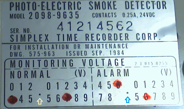
And this lead me to a question: For the smokes, I have four 2098-9636 heads on the 2098-9637 bases. On the back sticker of the heads, I see on the a blue section printed under the serial number on the sticker. The blue section says “Monitoring Voltage” which is split into “Normal (V)” and “Alarm (V)”.
What I find very confusing is that each sticker has a red dot on a different combination of numbers. Example: #1 – Normal = 2 and 6 ; Alarm = 6 and 5 #2 – Normal = 2 and 0 ; Alarm = 6 and 0 #3 – Normal = 2 and 6 ; Alarm = 6 and 3 #4 – Normal = 2 and 6 ; Alarm = 6 and 2
I didn’t find any specifics in the documentation, so thought I would throw this out there…
I found a 2098-9635 in my equipment collection which has a similar label. There is a dot between each set of numbers which I think is a decimal point. I drew some arrows in the picture below.
I think these voltage specifications have something to do with the sensitivity testing boxes used at the time for these detectors. The test boxes had a test point output for connecting a voltmeter. The red dots represent the voltage levels at time of manufacture for comparison with field measurements. The voltage reading was used with chart to determine if the detector was at correct sensitivity or was out of range.
Hi Retired STR-SG,
Quick question for you… Is it possible to put a pull station at the end of line of smokes so long as the proper terminating resistor is used?
I would think it would be fine since all the zones use the same circuitry… but I am concerned that the short of the circuit upon pull station triggering might damage the internal power circuity of the smokes. But I could be completely wrong too. :?
Not a problem. You can mix devices on the same IDC. In an actual installed system it is preferable to wire to the pull stations first and then to the smoke detectors. That way a removed smoke detector head cannot stop a manual device from creating an alarm.
Many years ago when 4-wire smoke detectors had a trouble relay to open the IDC loop in case of a failure those contacts had to be wired separately after all the devices. NFPA ruled that a removed 2-wire detector head was not a system failure. It is tampering with the system so mixing devices in any order was acceptable.
The next generation of panels using microprocessors use the fact that a pull station shorts the loop and a 2-wire smoke doesn’t to an advantage. Those systems can have an IDC that causes an instant alarm when a station is pulled but can start a verification cycle on a 2-wire smoke activation. This difference can also be used in sprinkler monitoring. Wire a flow switch to short the IDC for an alarm and add a resistor in series with the tamper switch to create a supervisory condition. The magic of software.
Hello Retired STR-SG,
Looks like a lot of good stuff got lost on the thread here unfortunately… I just noticed the site was back up again. Many thanks to TFP website team!
In the meantime I have been fiddling about with the panel and made good head way, tried several things and I think I have the hang of at least the basics. The documentation has been quite a lot of fun to learn… I can see a lot of time went into the design of the circuity to achieve all the card breakouts and not create overlaps.
I tried the march time card which I picked up on eBay and had that working, but I really wanted to try for the three temporal alarm. So I found a coder card and configured it alternating three dips on and three off to get the pattern. It is Ok but I’m not 100% happy with the result. The coder card seems to be operating the bit register walk based on an oscillator which produces too quick a pulse to the horns to get the proper sounding.
But now to my question… The coder card appears to control the signal card on the C bus with -0V pulses in the coded output (and hence the D25 removal on the 1007 controller), but this codes all signals in the cabinet (since they all pull -0V from C bus). Is there a proper way to code just one signal circuit on a 2076 Signal module? I think I can pull D2 on the coder feeding C bus, put D25 back in on the controller (thus a steady -0V when alarmed on C bus), and feed the coder module’s E (+V coded alarm pulses out) to M (+V in when alarm to ckt. 2) on the signal module.
Also, the coder runs through several cycles and then ‘coding complete’ lights. I assume there is a counter (IC 4?) that defines the number of times the card cycles. Is there an defined method to keep the coder from completing?
I’ll have to dig into IC6 on the coder a bit more tomorrow. I think this may be where the timing for the register is coming from and if I can slow down the coder, I think I will be happy with the result.
Your solution on changing to a positive voltage code feed to the signal module will work. The transistor that drives the positive pulses has a much lower current capacity than the one driving the C buss, so keep that in mind.
There was a 2001-3053 (part # 562-499) Temporal Code 3 module, but good luck finding one.
I found this solution on Fire Alarm Resources about making a 2001-3049 coder continuous. Is this the one you have? If not, it probably is similar circuitry. http://firealarmresources.com/simplex-2001-how-to-make-the-2001-3049-coder-continuous/
This references taking a wire to terminal 5 on the left hand motherboard which is system 0V. Since you don’t have a -8001 full size system you have to get 0V from another source. Of course, 0V comes to the module on PC Pin 15, so it is available on the coder board.
Hi Retired STR-SG,
Ok, cool. The 2076 signal card seems to only use he positive alarm voltage for the relay. The data sheet shows 8.5mA operating current for the relay on the 2076 and the 2N4403 on the 3049 is rated at 600mA, so I feel comfortable this should be Ok.
Indeed it is a 3049. Thanks for the link to the continuous code resource document. So it looks like my guess was right that IC4 is the counter. Yea, I can imagine that is probably quite rare. Well, with the schematic I might be able to build my own… They are only two sided boards. Sounds like a fun project.
Thanks for the link to firealarmresources.com… you had actually PM’ed me some document links. I’ve seen that firealarmresources.com page in google results, but looking at the page I must have written it off as one of the spam link aggregator websites and not something with content. But yea, that is a great resource.
As always, Thank you ever so much for your help!
-Cheers, Peter.