Notifier System 5000 - Power Supply Help (MPS-24 original version)

Hey all, it’s certainly been a while, doing well, I’ve just had a lot going on where making new videos has taken a back seat.

I recently rescued a Notifier System 5000 from scrap. The panel has the original version of the MPS-24 power supply (not the MPS-24A like most documentation I’ve found shows). I am having some trouble figuring out which terminal to wire to. I’ve been doing my research - almost no documentation exists for the original MPS-24 power supply, I am only finding documentation for the System 5000 and Sensiscan 2000 that features the MPS-24A.

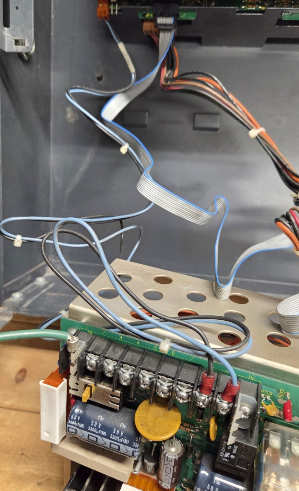
Here’s what I have been able to figure out so far based on continuity testing I’ve been doing.

  • Terminals 2 and 3 seem to be ground/earth, continuity testing reveals that these are tied together
  • Terminals 4 and 6 appear to be Neutral (-) In/Out, continuity testing reveals these are tied together. The MPS-24A has the Neutral terminals to the right of the Ground.
  • Terminals 5 and 7 appear to be the Hot (+) in/out, continuity testing reveals these are tied together.
  • Terminals 8 and 9 to the far right appear to be wired to something else on the panel, I did not remove as of yet)

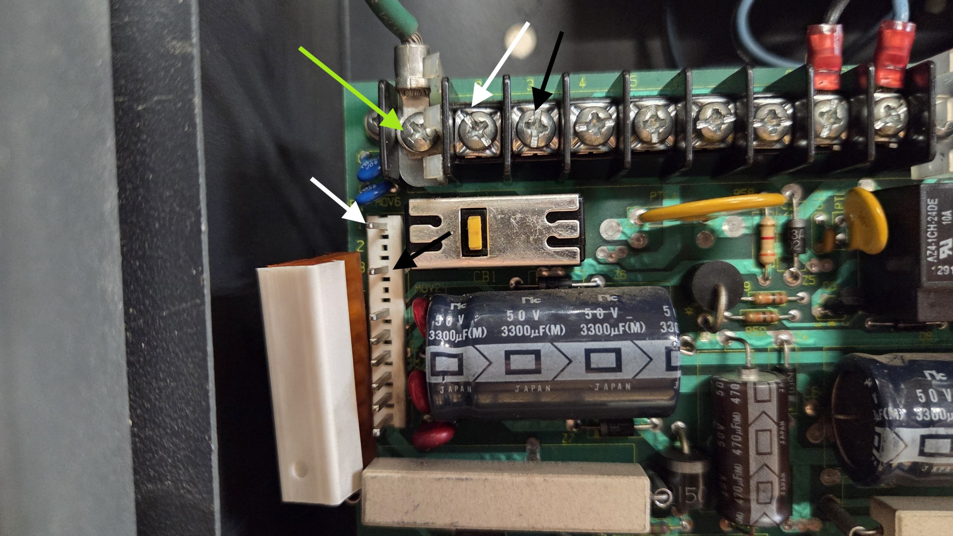
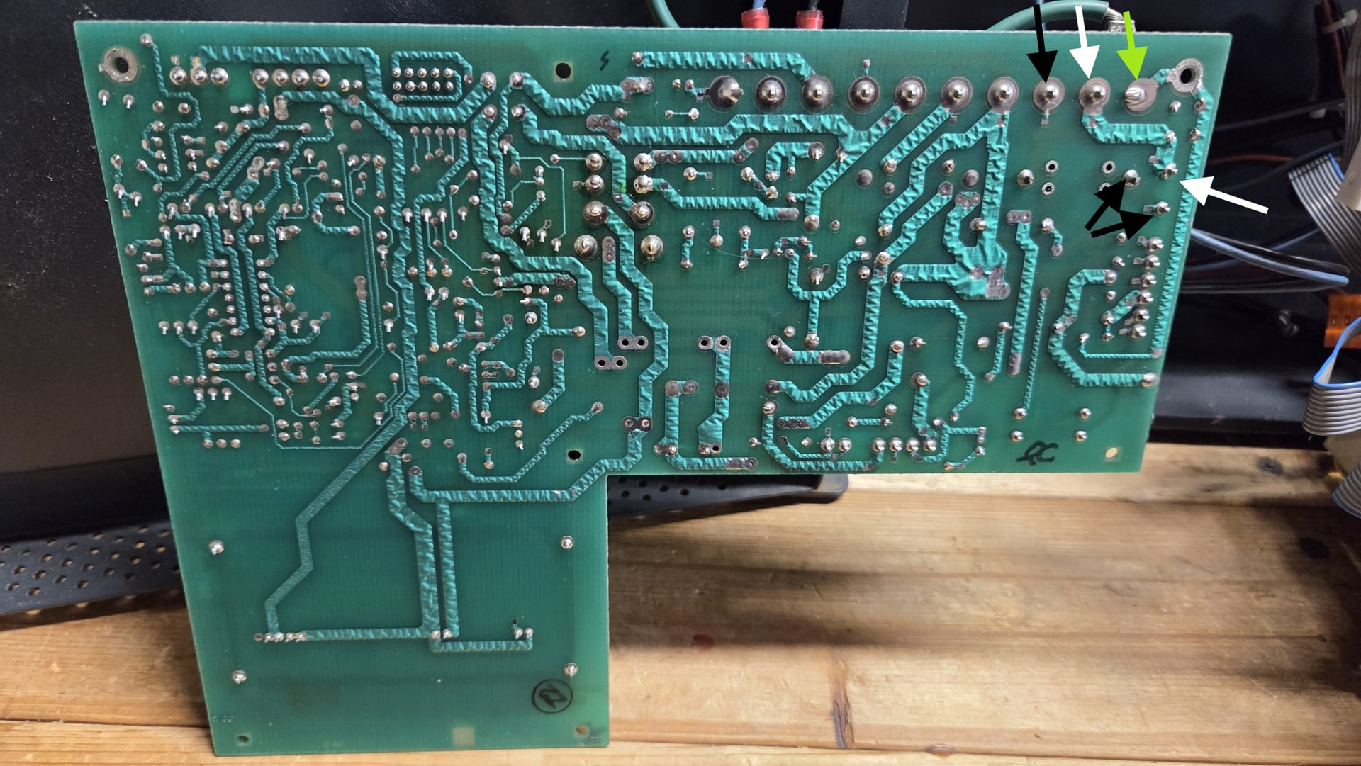
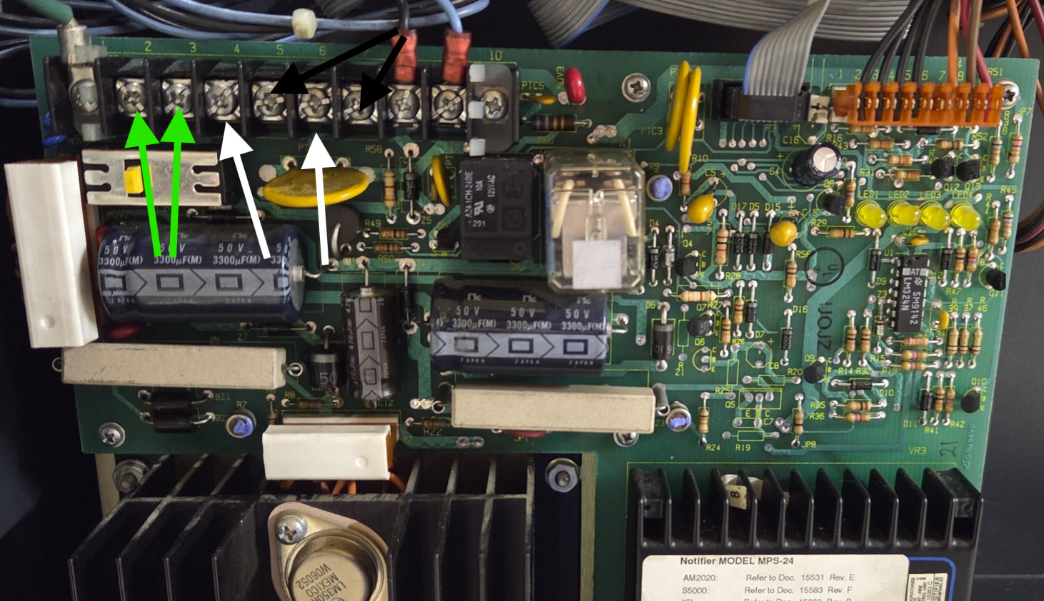
Below is a photo I took, the ground is marked with green arrows, neutral marked with white arrows, and hot marked with black arrows.

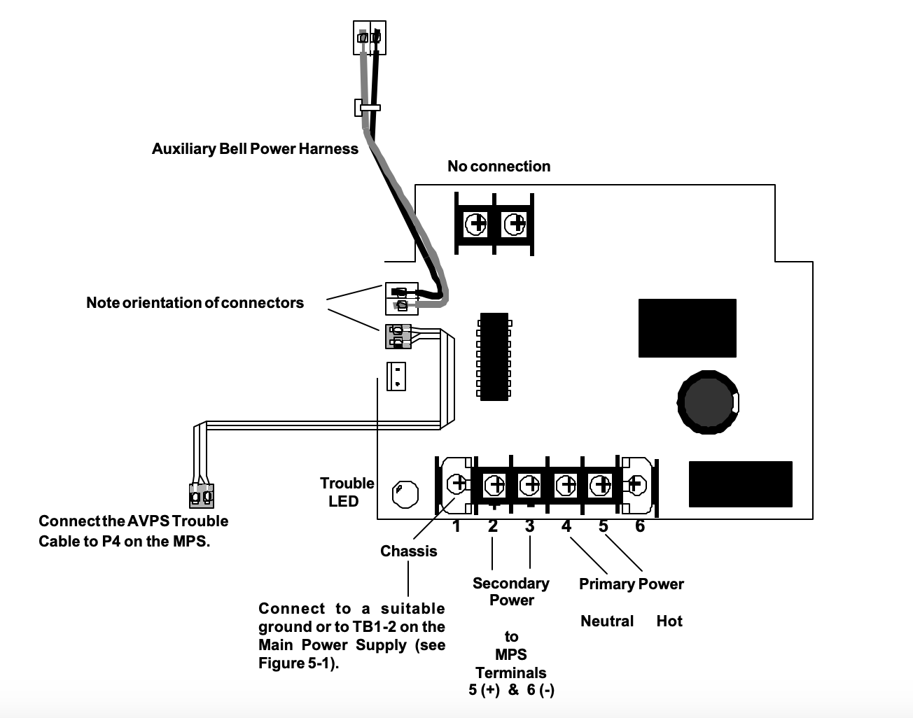
This seems to contradict what the MPS-24A wiring manual suggests. While terminals 2+3 are still the same (Ground). On the MPS 24A, terminals 4+5 are Neutral In/Out and 6+7 are Hot In/Out. (see page 2 of this data sheet: MPS-24A Main Power Supply Data Sheet)

Has anyone worked on these panels with this power supply prior? I wanted to double check prior to wiring anything high voltage up. Everything else seems to be good shape.

1 Like

First of all, nice to see your name on here again! I haven’t worked on this personally, however we do seem to have at least one doc for this thing: https://cdn.thefirepanel.com/docs/notifier/Notifier%20-%20Mps%2024%20Avps%2024%20Ps%20Product%20Repair%20Instructions.pdf

This doesn’t provide a TON of info.. but maybe a couple more model numbers to consider? I also can’t find anything else though. :confused:

Thanks Zach! Glad to be back here as well. I will continue digging around to see what I can find. That is the one doc I did find, but doesn’t seem to have much info on the terminals to hook up to. If anything, wondering if this power supply should be replaced with a MPS-24A.

I’ll continue taking a look and seeing if there is anything that I can find in terms of documentation (searching for other similar models such as the System 2500 and the Sensiscan 2000 seems to make mention of the MPS-24A power supply.

I’m going to take another look at the board to see if there is anything other circuits I can trace. As of right now, I have a gut feeling that Terminals 3 (Ground), 4 (Neutral/White), and 5 (Hot/Black) may be the ones to hook my main input into, but I want to really verify first.

Howdy! I found some old images from a couple Discords of the MPS-24 in action. They are kind of blurry - please excuse the quality. I hope this is what you are looking for.

Edit: I just realized that these are the wrong model. Oops. My apologies.


1 Like

Wow, that’s an oldie. Haven’t found much documentation on this particular version. It looks like 8 and 9 are a DC output to signals and such.

6 and 7 might be battery connections.

This leaves 2, 3, 4, and 5. Based on your metering, 2-3 would be earth ground, 4 would be neutral, and 5 would be hot. This would be similar to what happens on the MPS-24A.

This is probably completely wrong, but that’s my guess. Can always look on the backside of the PCB to see what goes where.

If I happen to come across an MPS-24 manual or wiring diagram, I’ll let you know.

Found this picture on facebook, hard to make out but it might give an idea?

Thank you! I have been doing some more metering, and have more results I found

Seems like terminals 4, 6, 8 (what I assume is Neutral) and 5, 7, 9 (what I assume is Hot) are interconnected. The wires connected to terminals 8 and 9 are both going up to the CPU board (I have not removed these wires since obtaining). These appear to be the Bell Power wires, at least what one of the manuals I found indicates, even when connected to an MPS-24A

Been doing some further metering at one of the wiring harnesses, particularly the one on the right side of the power supply labeled P4 (appears to be the main power harness). When I have my probe on terminal 4 (which I think is the Neutral wire) on the PCB and one of the black wires on the harness, continuity testing seems to indicate these are connected. When my probe is on terminal 5 (what I think is the hot wire, which is black) and I tap on the brown wire on the harness, it seems like these are connected.

Pretty baffled by these test results.

I have done some research, and still no luck finding any info on this version of the power supply. I found a reddit post (Link here) with a System 5000 (see the 2nd photo). I can barely make out the wires, but it appears to be Ground, Neutral, and Hot right next to each other.

Please let me know if you have any findings on this older power supply.

Thank you for sharing the photo! Taking a look, and it appears the order may be Green, Black (hot) and White (neutral), though it is hard to tell. I dont think it would be likely that hot would be next to Ground.

8 and 9 are DC power, typically for powering signals. The CPU has 2 NACs, so that’s what that harness is for.

The orange connector is just 24V, 5V logic, and commons that go to the CPU. No AC on those and I don’t think those dictate what the screw terminals do.

The AVPS-24’s wiring might be a hint on how it goes. These were out with the original MPS-24s.

1 Like

Oh wow I haven’t seen you around these parts in quite a while, glad you still are passionate about the fire alarm collecting hobby

1 Like

Thanks for this diagram! I’ve been comparing this to the diagram of the known MPS-24A, seems like terminal 5 is hot (+) and 6 is Neutral (-) on the MPS-24 “classic”.

So continuing to figure this out, and based on how the AVPS-24 is wired, thinking the following may be the case.

2+3 - Ground (Green)
4 - Neutral (White) - from 120vac main
5 - Positive (from the AVPS-24, not sure if it’s 120VAC)
6 - Neutral (from the AVPS-24, not sure if it’s 120VAC)
7 - Hot (from 120vac main).

Still confused on how 4, 6, and 8 and 5, 7, and 9 seem to be tied together according to my multimeter’s continuity testing feature, especially if 8 and 9 are supposed to be DC power. What you showed me from the AVPS-24’s manual seems to be a great hint.

Good to know about the orange harness I photographed about it being 24VDC.

Hey everyone,

It’s been a while since I posted anything on this topic, I finally had a chance to take another look at the board and try and figure this thing out despite lack of documentation. I appear to be incorrect on my initial guess on the terminals. Was able to further analyze the board, and here are my current guesses on the terminals…

  • Terminal 1 is the Ground - there is a lead already on the panel
  • Terminal 2 is the 120VAC neutral - ties to Pin 1, which ultimately goes to the transformers. There was a white wire still in this terminal when I rescued the panel.
  • Terminal 3 is the 120VAC hot - ties to Pin 3, which goes to the transformers. The battery disconnect/power disconnect switch is also tied in between the terminal and the pin going to the transformer. Pressing the battery disconnect switch appears to interrupt the circuit, as expected.

The odd part is when test 2+3 for continuity when the transformer harness is plugged in, the continuity test appears to report these two are tied together. When the transformer harness is unplugged, continuity testing reports these are not tied together. Some basic knowledge of electronics suggests that this behavior is normal (correct me if I am wrong).

I recall based on what I was able to see from the photo that @dewpoint8900 had shared of one still in service, appears the ground, neutral, and hot were all the way to the far left.

This leads me to now believe that 4-9 are all DC outputs (still not sure which one goes to the battery, I now know 8+9 go up to the panel as the bell circuit. Terminals 4, 6, 8 are tied together, and appear to be negative, and terminals 5, 7, 9 are tied together, and appear to be positive (also based on the diagram for the AVPS-24 that @dewpoint8900 had provided. They are not tied to terminals 1, 2, and 3.

Here are some more photos of the power supply, with some updated annotations.

An updated photo of the terminals, with colored arrows pointing to which terminal I think is which. Also to the left are the pinouts to the transformers behind the power supply.

Rear of the power supply assembly, with the transformers on the back. They go from 120Vac to 28Vdc

The rear of the power supply board - with arrows pointing to which traces I think are hot vs neutral.

I also found this old topic, but the links in this topic are no longer working: Notifier S5000 AC wiring - Fire Alarms - The Fire Panel Forums

Any additional verification prior to me wiring this up (and hopefully not releasing any magic blue smoke) is appreciated. Thank you to everyone who has helped me out thus far.

Yeah, that makes sense, the transformer’s secondary will have pretty low resistance, hence the DC continuity reading you get between those two terminals with the transformer hooked up.

1 Like

Seems to be getting closer! Assuming terminals 4-9 are all DC, then I’d imagine one pair is for the batteries, and the remaining 2 are DC outputs. That would match how the later MPS-24As were (those provided 2 pairs of DC outs, one was resettable).

I’m fairly confident 4-5 would be the battery, since the MPS-24A has battery terminals near the AC input (also the S5000 pic I sent, seems the batteries wire to 4-5). That would leave 6-7 and 8-9 to be DC outs.

Also, that button near the AC terminals is a circuit breaker. I assume it’s for AC; it’s used on a lot of Notifier/Fire-Lite panels from this time period. The MPS-24A had a battery fuse, but I don’t see one on the original MPS-24, so be careful with batteries.

Came across this old MPS-24B power supply, these are mainly for System 500s. That 6-terminal block has 2 pairs of DC outs and then battery terminals, kinda like the MPS-24.

1 Like

This information has been very helpful! I learned something new about the transformer - it’s been a while since I’ve tinkered with electronics. Thanks for the info @ThreePhaseEel

@dewpoint8900 , The MPS-24B looks very similar in layout to the “Classic” version of the MPS-24 that I have (though I understand it would actually be mounted upside down in the can on a System 500), but seems to confirm my theory of the Neutral being to the right of the ground (I wouldn’t want the Hot being right next to my ground). Feeling confident that we are close to solving the mystery, and that 1, 2, and 3 are Ground, Neutral, and Hot respectively. I am still a little skeptical since the DC terminals would be under the 120VAC shield that would usually go over the terminals, and the Ground terminal that I mentioned would be outside of that shield.

Hi everyone, got good news. Got the panel working!

I successfully confirmed that Terminal 1 is ground (with existing pigtail), Terminal 2 is 120VAC Neutral, and Terminal 3 is 120VAC Hot.

Still not sure about the battery terminals, but I suppose 6+7 may be the terminals since they output 24VDC (while 4+5 dont appear to Output 24VDC, but can act as a 24VDC input when the 120VAC is NOT applied to the panel).

Thanks to everyone who has assisted. No “magic blue smoke” was released while figuring this out. :wink:

*EDIT: 6+7 appears to be power for 4-wire smoke detectors. My apologies

@Johann you still got these pics by chance?