Hey everyone,
It’s been a while since I posted anything on this topic, I finally had a chance to take another look at the board and try and figure this thing out despite lack of documentation. I appear to be incorrect on my initial guess on the terminals. Was able to further analyze the board, and here are my current guesses on the terminals…
- Terminal 1 is the Ground - there is a lead already on the panel
- Terminal 2 is the 120VAC neutral - ties to Pin 1, which ultimately goes to the transformers. There was a white wire still in this terminal when I rescued the panel.
- Terminal 3 is the 120VAC hot - ties to Pin 3, which goes to the transformers. The battery disconnect/power disconnect switch is also tied in between the terminal and the pin going to the transformer. Pressing the battery disconnect switch appears to interrupt the circuit, as expected.
The odd part is when test 2+3 for continuity when the transformer harness is plugged in, the continuity test appears to report these two are tied together. When the transformer harness is unplugged, continuity testing reports these are not tied together. Some basic knowledge of electronics suggests that this behavior is normal (correct me if I am wrong).
I recall based on what I was able to see from the photo that @dewpoint8900 had shared of one still in service, appears the ground, neutral, and hot were all the way to the far left.
This leads me to now believe that 4-9 are all DC outputs (still not sure which one goes to the battery, I now know 8+9 go up to the panel as the bell circuit. Terminals 4, 6, 8 are tied together, and appear to be negative, and terminals 5, 7, 9 are tied together, and appear to be positive (also based on the diagram for the AVPS-24 that @dewpoint8900 had provided. They are not tied to terminals 1, 2, and 3.
Here are some more photos of the power supply, with some updated annotations.
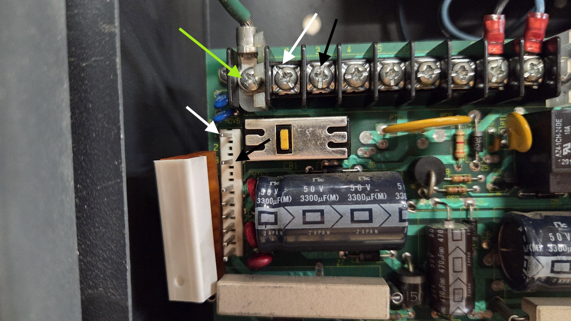
An updated photo of the terminals, with colored arrows pointing to which terminal I think is which. Also to the left are the pinouts to the transformers behind the power supply.
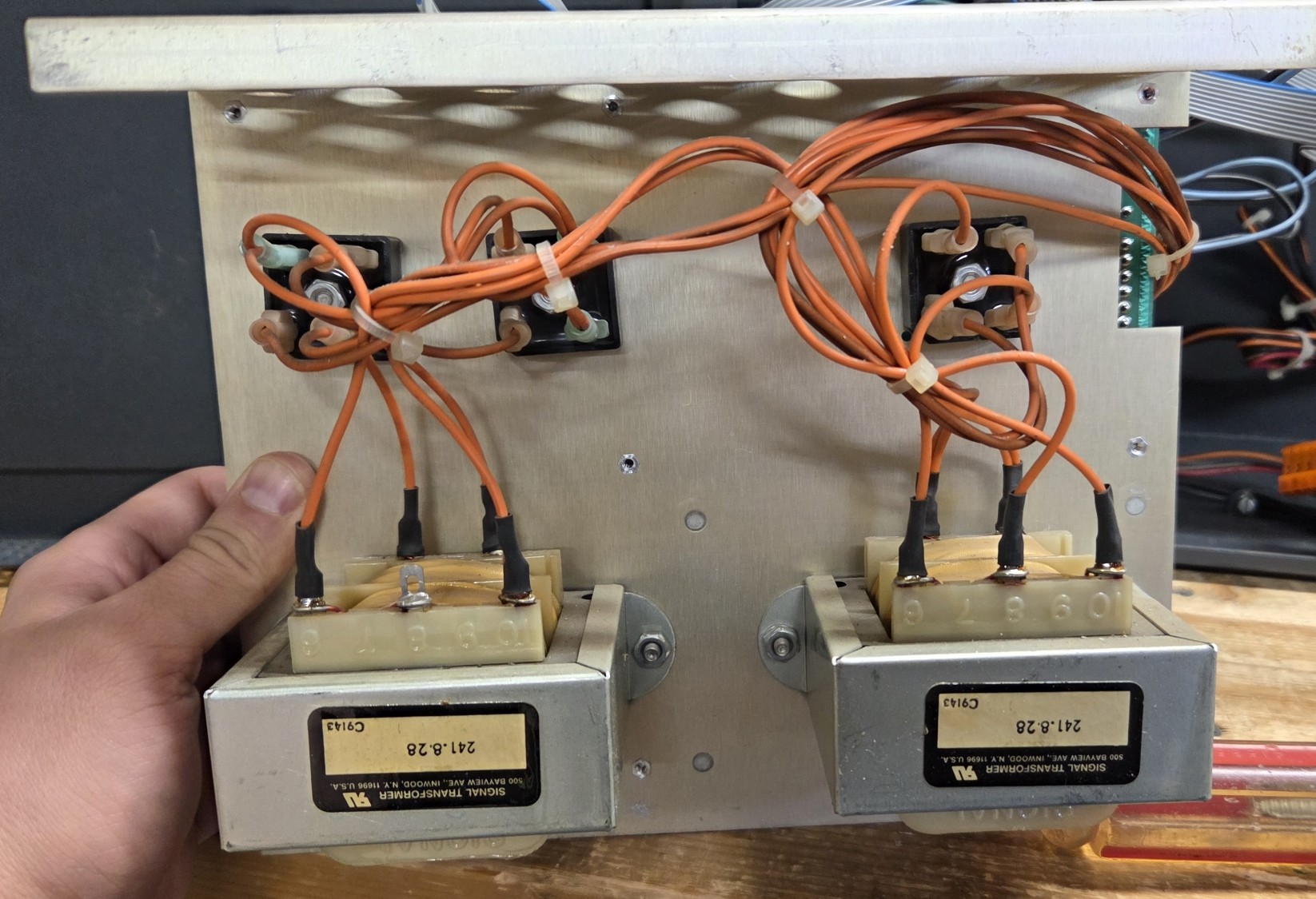
Rear of the power supply assembly, with the transformers on the back. They go from 120Vac to 28Vdc
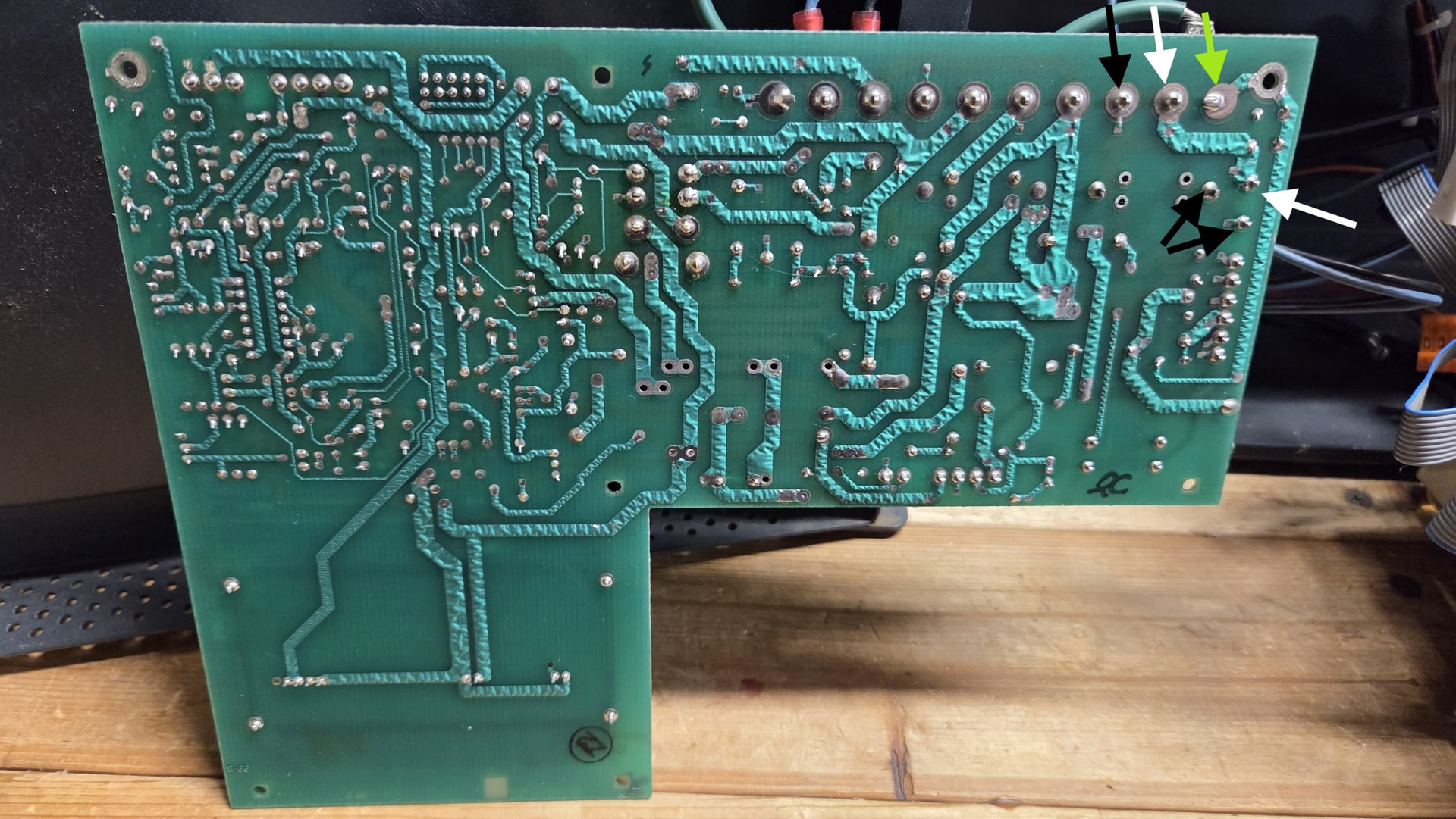
The rear of the power supply board - with arrows pointing to which traces I think are hot vs neutral.
I also found this old topic, but the links in this topic are no longer working: Notifier S5000 AC wiring - Fire Alarms - The Fire Panel Forums
Any additional verification prior to me wiring this up (and hopefully not releasing any magic blue smoke) is appreciated. Thank you to everyone who has helped me out thus far.