Hello! It’s great to be back on the forums. I’m Fahrenheit4051 on YouTube, and was Simplex 2901-9833 on the old forums. Anyway, I have a small, used Simplex 4207 panel. I’d really like to test it, but I’m not sure what to do. I did bring plenty of photos, though.
For starters, here’s the entire inside:
Here’s the main board:
It has five cards. The slots are labeled: Signal silence, low battery, Earth (which I’m guessing means “ground”), Zone 1 and Zone 2.
Here’s a close-up of the on-board screw terminals. I’m guessing the Z# terminals are for the IDC zones, and the G+/- are for ground.
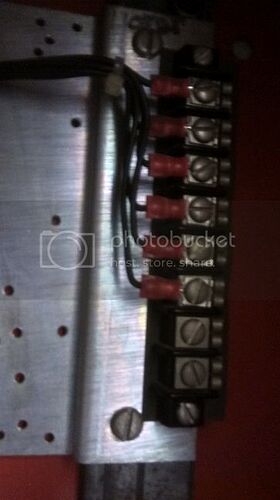
Here’s another set of terminals:
These screw terminals are located apart from the main board:
They’re labeled 1 through 8. I’m guessing they could be for the NACs.
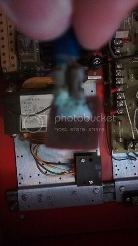
These components are located below the main board:
I know the device on the right is a transformer, and I’m guessing the black thing is a sort of heat sink. But I have no clue what the small screw terminals are for.
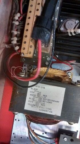
This part has me confused:
I wouldn’t be concerned with these terminals if it weren’t for these two loose wires sticking out. As you can see, one of them has an in-line fuse.
Here’s the positive wire from the component described above:
It’s pretty badly corroded. I’m guessing the negative wire also had one of these red plastic squares, too. Wait… Just realized this while writing… Nasty white corrosion? Positive and negative? Battery hookups!
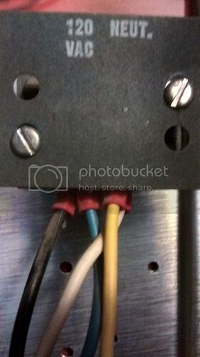
Here are the AC terminals.
This part scares me the most. I really don’t want to fry myself.
Here’s the left display panel:
No batteries = Trouble.
Here’s the right display panel:
Here are the hookups for the display:
If you’re curious, here’s the ID tag, too:
It also came with some blueprints from Simplex. If anyone would like to see those, I could photograph or scan them some time in the near future.
Thank you for any help you can provide.
That is a 4207CK. The “C” indicates the top circuit board which is the motherboard for the plug in modules and other components. The “K” indicates the lower section which is a standard 4207 power supply/charger assembly, a K module. The “C” board is unique to this system only. The “K” module was also used in the full size 4207 systems. The serial number tag shows the Wiring Diagram date of 3-10-77. So this system is 38 years old.
As you can see this is a 2 zone (IDC) 1 signal circuit (NAC) system. If you have some documentation that came with the system you probably have more information than anyone else. However, I can dig around to see if I have anything on his system. Don’t bet on it.
Here is some information purely from memory. The zone boards came in 2 types, a contact only zone and a 2-wire smoke detector compatible zone board. The 2-wire smoke board is easy to identify, it has an IC chip on it. The contact only board does not. The contact only board uses a 200K ohm EOLR. The signal circuit monitor board might be the same board so the signal circuit also takes a 200K EOLR. The 2-wire smoke board uses a 2.2K ohm EOLR.
The 8 terminal strip away from the board I don’t think is for NACs. There is only 1 signal circuit on this system. I believe these are for annunciator connections.
Yes, the black finned assembly is a heat sink. The bridge rectifier and main regulator transistor are mounted on it. The board below is the power supply control board. The screw terminals are for landing the wiring harness to the other system components.
Check the documentation to be sure but I think the G+ and G- terminals are to land the signal circuit. That could be for Gong + and Gong -. The “G” designation is a hold over from even older systems when the NAC was called the Gong Circuit. Easy way to find out. Once you power up the system put a 200K EOLR across G+ and G-. If I am correct the Signal Circuit Trouble light should turn off.
Be aware that some of the lamps may be burned out. Luckily, these were standard lamp assemblies made by Industrial Devices. It think they are part of Chicago Miniature Lamp company now. But similar lamps are available.
When I skimmed through the documentation, I did remember seeing the NAC labeled “gong circuit”. I might try to test it soon. Thank you very much!
One quick question - Would it be okay to use speaker wire, or should I stick to solid copper wire?
Of course there are very strict requirements in the National Electric Code for wiring fire alarm systems that protect life and property in buildings.
For a hobby system speaker wire will work. That probably is stranded wire so be sure that misplaced strands cannot touch other wires or other terminals. It just takes one misplaced strand to ruin your day - and your panel. I use crimp on terminals with stranded wire or tin them together with a soldering iron.
Crimp-on terminals… Are the ones that are shaped like forks okay?
A fork shape is one style. There are also a loop end styles. Crimp on terminals are available in several sizes that accommodate various wire gauges. There are also butt splices that are used to join wires. I have a Lowe’s close to me and get them there.
Best results are obtained with a crimping tool. There are several types. Some are included on wire strippers. Example below.
Thanks again for your advice.
Alright! I just powered up the panel today. A few lamps are out, but the trouble piezo and silence switch works. Now, I’d like to wire up a pull station, but I don’t know how to hook it up to a zone, since they are labeled Z1, Z2, Z3, and Z4, with no indication of polarity.
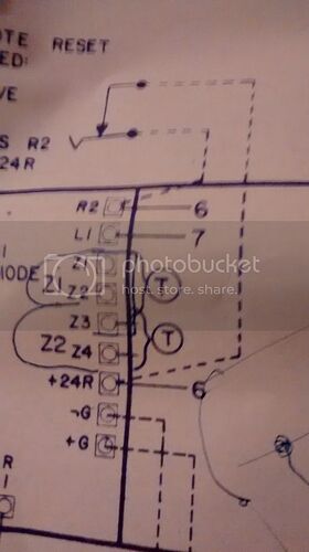
However, I do have a document that shows how to wire the terminal strip:
Problem is, I don’t know exactly how to interpret this. The scribblings seem to imply that Z1 and Z2 are Zone 1, and Z3 and Z4 are Zone 2, regardless of polarity. If I’m correct, then it should be fine as long as I keep the polarity of all the devices on that IDC consistent.
If you have the complete drawing set, the “T” in the circle refers to the section of the package with the typical circuit drawings. That may show the polarity. The terminals with a short line with a number denote conductors in the factory wiring harness. Pull stations for conventional systems are just a switch contact that shorts the between the zone wires so the polarity doesn’t matter, especially in a hobby system.
In that same document, the “T” symbol is denoted as meaning that any unused circuits must have an EOL resistor to prevent troubles. So essentially, I should be able to wire a pull station up to Z1 and Z2 to create an IDC, right?
Also, I have the contact only board (I didn’t see any integrated circuits), which takes 200K-ohm resistors. I bought 220K-ohm resistors, the closest I could find. Should they be okay, or should I wait until I can find ones that are exactly 200K?
Yes, as the drawing shows, Zone 1 uses terminals Z1 and Z2. The last time I saw the drawings for a 4207CK was about 40 years ago.
The 220K should work. The worst that can happen is that the panel would show a trouble. The circuits are made to accept the normal tolerance of the parts used. A 200K ohm 10% tolerance resistor at the high end of its range would be 220K ohms. If the circuit turns out to be finicky, two 390K ohm resistors in parallel would be 195K, which is within 2.5% of design value.
Okay, great. Thanks!
Zone 1 ended up being fried, but zone 2 works perfectly! I just uploaded System Test 1, so thanks again for all your help!
What are the symptoms of it being “fried?” The most likely issues would be a foil burned off of the main motherboard or a bad part on the zone 1 daughter card. Probably one of the transistors is bad. Someone with a decent knowledge of component level troubleshooting might be able to repair the daughter card.
The panel didn’t go into alarm when I hooked it up to a pull station. That’s about it. Perhaps that’s why it was removed.