Hello, my 2001 has several jumper wires between slots cut, and some diodes on the zone cards are cut. The panel has 8 zone cards. 3 of them have diode D19 (I think) cut. I will have a picture below. However, the remaining 5 also have D29 cut as well, and a picture will be provided below. The system has no coder card, and none of the components on the control card appear to be cut.
Many 2001 systems have supervised annunciator outputs, including yours. If there was not an annunciator in the system the supervision for the entire panel can be disabled by clipping R8 on the 2001-1007 control module. If the system had an annunciator but not all zones had a lamp the supervision can be disabled by zone. That is done by clipping diodes D19 and D29 on the 2001-1017 zone modules. My documentation has a discrepancy as to which diode is attached to which zone. The schematic shows D19 associated with Zone 1 on the card and D29 associated with Zone 2 on the card. Another memo I have shows just the opposite.
These diodes would also be clipped if several zones were connected to one annunciator lamp. The supervision circuit on the zone card draws a tiny bit of current through the lamp. If several zones were connected in parallel the lamp could glow a little. The the diodes would be clipped on all but one parallel zone to prevent the lamp glow.
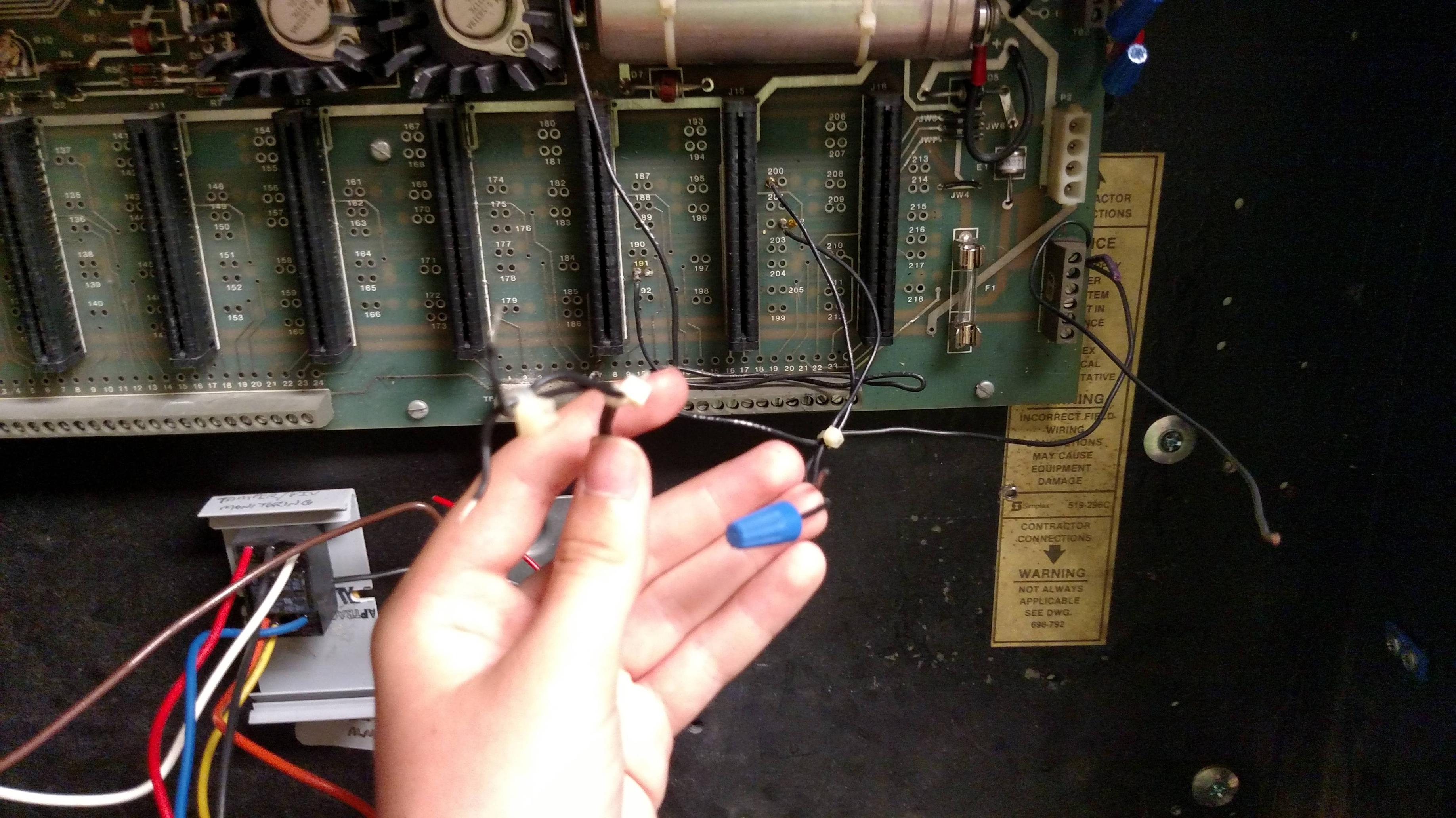
Be aware that the raw power module has a bridge rectifier in addition to the transformer. The P2 connector power input to the motherboard is a DC input.
The jumper wires on the motherboard are for some custom operation. There are some black wires that look to be either factory installed or very neat technician work. I will PM some document links so you can figure out what you want to do with these.
A previous picture you posted shows the panel has a OP/SP module in the second row. That was to supervise a second AC power source in a panel that did not have batteries.
Yes, there was an annunciator for this system. As for the jumpers, they seem relatively straightforward.
For the transformer, is there a module that has both the bridge rectifier and transformer that I should look for or will any transformer and bridge rectifier work?
There was a steel plate that mounted in the lower right corner of the cabinet. On that plate is the AC input terminal strip, transformer, fuse holder, bridge rectifier, and the harness to plug into the motherboard. I searched around for a picture or drawing but can’t find one.
The panel was capable of multiple signal cards so the original transformer was 24 volts at probably 8 or 10 amps. The fuse is 10 amps according to the parts list so that puts it in the low voltage side of the transformer. The bridge rectifier was the 20 amp bridge we used in many power supplies. The 4 pin plug that fits the motherboard DC power input and the battery harness connectors is in the Molex MLX series connectors.
Finding the original parts would be a miracle. Best you can do probably is start gathering generic parts as you can find them.
This transformer popped up in my email from Ebay. It looks like it would do the job. And it’s on sale. However, the shipping costs more than the part. http://www.ebay.com/itm/400940475859
Ebay has a big selection of 25 amp bridge rectifiers. Radio Shack might still sell fuse holders. The Molex MLX connectors probably will need to come from an electronics parts dealer.
I have an old 2120 power supply around somewhere. It used the same Simplex part number rectifier as the 2001 expanded repack. I will look for it and get the manufacturers part number from the bridge. Then I can find the specs. Just guessing, I bet it will be at least 100 volts.
I found something else I have with the same Simplex 374-034 part number bridge in it. It is an Edal B682-40-1, 400 volt 25 amp bridge rectifier. So there is the spec.