→ I configured a 301 Redirect and made a custom 404 page.
NewAgeServer and I are wondering if you even looked at the Alertek 5001 schematics. Because that is a complete and functioning panel that doesn’t require a microcontroller.
It pretty much boils down to just ripping the design and make it work with multiple zones. If you want to do more than continuous, pulse and march time codings, you will need a microcontroller or something similar to pulse the relays at different timings.
I did look at the diagram, and the panel does have a coder (not shown in the diagram because there is no way to represent it). The coder would go in before the Horn NAC. Again, I did look at the 5001 schematic, but I don’t want to copy NewAgeServer’s idea, but want to make my own (including the schematic).
I revised it a little bit:

You still have not labeled your positive and negative wires so I don’t know which direction anything is going.
It’s not the fact that you are not copying that panel design, its the way the circuit works so you really have no choice.
What are you going to be using to pulse the NAC’s?
It is a strobe light flasher that includes march time (slow and fast), continuous, and a few interesting new coding options.

Your alarm LEDs are still wired in series. They will burn up. You need to wire them in parallel or else it won’t work at all. But be careful – if you wire them in parallel, all four will light up at the same time. In this case you will need to put a diode in series – essentially the same way your LEDs are wired now.
and the audible LED too.
Do I need all 8 Diodes? Also what “kind” of diode (like resistance for resistors)
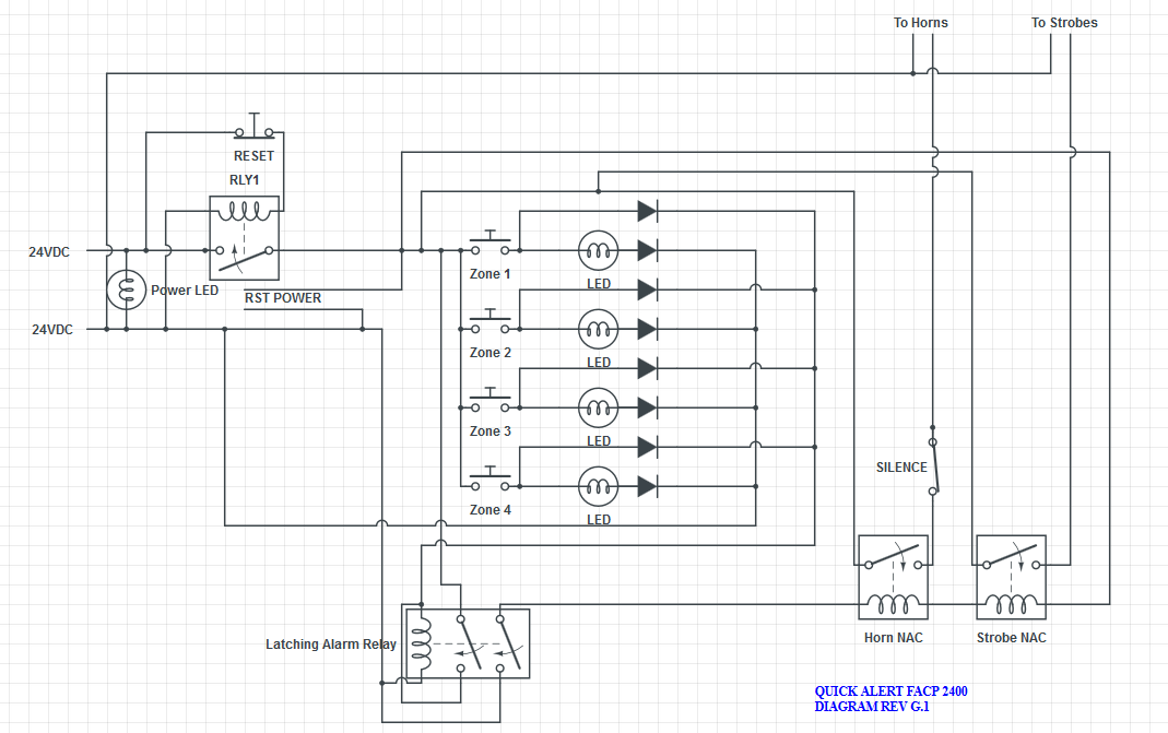
Much better, but you don’t need a diode after each LED. LED means Light-Emitting Diode…so having a normal diode after each LED is pointless.
Also, for the record, you’re using the symbol for a lamp. The symbol for an LED looks like the diode symbol but it has two arrows next to it that point away.
I know the symbol is wrong, as said in a previous post. Circuitlab’s LED symbol is way, way too big.
What kind of diode would I need?

I’d say use a 1N4001 diode.
Also you’re gonna need to put a resistor in series before each LED… For 24V I’d recommend 5.6k, 1/4 watt, 5% tolerance.
OK. I believe all the LEDs have built in resistors though.
Final Revision (It seems)

Looks good but you forgot your LEDs.
Also, a suggestion – change your Silence switch to DPDT and add a Silenced LED which does not shut off until the switch is flipped back to normal. That way you won’t forget to un-silence it after you reset. ![]()
The button I have is latching and actually is dpdt with an led so I better update that. Sorry for any mistakes this was types on my phone.
You should note that smoke that 2-wire smoke detectors will not work on your system and neither the Alertek 5001.
I know. If you are referring to my signature the 2424 is a four-wire detector.
I have a couple of questions.
-
If that red coding square is a button, how is that going to chance the codings?
-
Where are you going to get 4-digit 7-segment display clock? If not, then how are you going to design it yourself?
-
Once you get the clock mechanism installed, how are you going to be able to set the time?
It is a clock module powered by 24V and there is a pinhole button in the corner of the control panel.
The coder (Not shown in the schematic because the Circuit Lab would not let me) has two terminals to connect to a button. I would change the codings by putting it in alarm, and pressing the button to change the codes.