Simplex 2001 - Wiring the motherboard jumpers

I just received a Simplex 2001 today from a technician. Never thought I’d own one of these pieces of Simplex history but here we are. I tried looking up documentation online, but couldn’t find exactly what I’m needing to get this operational.

It’s in great shape and is from 1982. The pictures I took show it how I received it in what I assume is the original set of cards in the order they were wired in. There are a few black jumpers on the main board, but I believe some of them are missing, as there are a few holes with solder in them but no jumpers.

I would like some help in trying to figure out where I need to place jumpers to get the panel going. I have some extra cards as well, such as dual zone cards and a dual signal card. Not sure how much hassle it would take to get a few of these going but for now they are extras. I have ordered a march time card that I plan to use along with the dual signal card, but for now I’m just trying to get it going in the configuration that I received it.

If anyone could help point me in the direction of what jumpers need to go where, I’d appreciate it. I don’t have the correct jumpers, so for now I plan to just use some wire I have to make my own. I’m not going to solder them in yet, just place them where they need to go.


2 Likes

Congrats on finding one of these panels, they are becoming very difficult to find and are indeed a significant piece of STR history. Appears to be almost mint as well.

So, it appears as if your panel is set up with 4 zones, 1 signal circuit, and a meter module. Now, with the way your panel is currently configured, you do not need any jumper wires running between the cards (besides the jumpers on J2, those are there to make the meter module work. If you want to keep the meter module, keep those jumpers in place. The meter module must be in J2 as well, as this is one of the design limitations with the 2001). However, as far as the zone cards and signal cards, with the way it sits right now, you don’t need jumpers. You can connect a pull station to a zone, and the panel and signals will activate (without coding) as the zone card sends power to the signal card through an internal bus on the motherboard rather than through jumpers.

It seems like you are looking to add a 90BPM marchtime card, so for that, you will have to add jumpers. I have a pretty good idea on exactly where you will have to place the jumpers, so I can try to help you with that. I also have a good idea on how to wire this panel (like connecting signals and devices to the zones), so I can help with that too if you would like.

It also seems like this panel has its original filtering capacitor, which I’m willing to bet is bad by now. The filtering capacitor is that large blue capacitor on the top right of the motherboard, and it is a part of the panel’s rectifier circuit. It essentially converts full-wave-rectified DC power to filtered DC power. However, these tend to go bad as they are oil-filled electrolytic capacitors, which dry up over time and cause the panel to output full wave rectified power. So, you’ll have to find a new capacitor and solder it on if you would like this panel to output filtered DC.

But once again, congrats on obtaining this beauty. I am more than happy to answer any questions you have about it, and when you are ready to wire it up, let me know! I am happy to help.

Thank you, I never thought I’d have much luck finding one! A Simplex technician I know sent it to me for free, along with the extra cards, and I should be getting a 4004 and a 4020 as well. I’m very passionate toward the history of STR. I also have a 4001 and a 4010 panel, both of which are in almost mint shape. I’m also well versed in electronics and troubleshooting/repairs and have experience with other fire alarm panels, both conventional and addressable. I’m 20 and plan to get into the fire alarm/low voltage field by next year.

Yes, that’s how the panel was when it arrived to me. I assume it’s in it’s original configuration. It was supposedly fully functional with that card order. I see, I heard that the meter module can only be used in J2. Interesting. What makes me wonder a little bit is why some of the jumper holes have solder, like they had jumpers at one time. That’s what speculated me that I was missing jumpers, which is why the panel wasn’t working. But it’s possible that the panel was once set up with a different card configuration in the past as well. As it sits right now, when I apply power, the green power LED on the main board comes on. Nothing else happens. All of the cards are seated in place. Interestingly, if I swap the main control card from the one that came in the panel to the extra one, the same behavior persists although the system trouble LED on the control card is lit. That light is not lit on the original control card. I’m getting around 13 volts AC on the secondary of the power transformer. I’m getting around 30 volts DC on terminals 1 to 5 and 1 to 6 on TB4 on the top left, so the voltages seem to be there.

Thank you, help with that would be appreciated once I get the march time card. I ordered one tonight. From what I remember, each card gets a certain number of terminals on TB1 and TB2, both for the zones and the signal circuit outputs. Do you know if it’s possible for me once I get the panel going, to swap out say one of these single zone cards with a double zone card, or the single signal circuit with the dual signal circuit card, without needing to add jumpers? I’ve been trying to find detailed wiring information online and I can’t come up with too much for how the jumpers are used relative to what cards are used. Eventually, I will ideally like to add the double signal circuit card, possibly a few dual zone cards, and the 90BPM march time card.

I bet it’s bad too. Same thing happens on antique radios when the filter capacitors dry up, you get hum in the audio due to lack of filtering after the rectifier. Sprague made quality capacitors, but I will definitely change it down the road, and just for kicks I will connect it to my capacitance bridge after it’s out of circuit, which can check paper and electrolytic capacitors for DC leakage current as well as capacitance value. Handy when working on old gear.

Thank you again, I’m really appreciative I have been able to come to own such a beautiful panel, both in condition and historical significance, and preserve it from being lost to the scrap pile as so many of these have been. I plan to hopefully mount this one on the wall, with a few devices connected to it for a demonstration system, like I do with my other panels.
Here’s more detailed photos of the motherboard and the jumpers if you wanted to look it over, and the main control card as well.


Uploading: 100_1682.JPG…
to

Absolutely! I share the exact same passion when it comes to older Simplex equipment and their history. I am very fond of anything Simplex from the 1990’s and prior, and have 2 4208’s, 2 2001’s (a repak and an 8001) and a 4010. I’m currently working on restoring a large 15 zone 4208 from 1976, and have plans to work on my 2001-8001 next, as someone cut the wire harness inside of it. But hopefully you can get the 4004 and 4020, those are excellent panels. I’ve always been fond of the 4020, as my elementary school had one and that was the first system I was really ever exposed to. Best of luck with getting in to the fire alarm field as well. I’m 21, and was planning to do that but opted to go to college instead for Computer Information Systems and am now in my 3rd year.

I honestly could not say as to why there is solder in some of the jumpers holes. I highly doubt they would have removed features when it was installed. However, it is possible that when putting this panel together at the branch office back in the day, the specifications for the system were changed last minute when they already started adding the internal wiring. Either that, or someone messed up at the branch office or factory.

So, I’m a little curious about the trouble lights not coming on with the first control card…I know the transformer is connected right, as it uses one of those one-way connectors that can only go in to the motherboard one way. You don’t have any end of line resistors connected, right? Are any of the trouble lights lighting on the zone cards and signal card? If not, and if there are no resistors connected, there may be something wrong with that first card. Come to think of it, your zone cards and signal cards may be class A only…would you be able to tell me the part numbers of your zone and signal cards? I can figure out what they are exactly from the 6 digit part numbers. If it is class A, resistors may not even matter.

It is very much possible to swap a single, signal circuit or zone card with a dual. You do not have to add extra wiring or jumpers, however, the way your zone(s) and signal circuits(s) would land in the panel would be different. Each card in the 2001 corresponds with 6 terminals on the bottom, going from left to right. So let’s look at the zone card for example. If you have a class A single zone card like I think you do, the first two terminals would be your circuit going out (B side), and the next two would be the circuit coming back to the panel (A side). The 5th terminal isn’t used, and the 6th is the positive output for the corresponding zone light on a 4300 series annunciator. If you swap it out for a dual zone card, there is no class A wiring. Instead, it is all class B. The first two terminals would be the first zone, terminals 3 and 4 would be the second zone, and the last two terminals remain the same (not used and annunciator).

Also, if you are going to add a marchtime card, you have to cut D25 on the main control card. That diode has to be cut in order for the main control card to apply power to the marchtime card.

That’a awesome! Simplex Time Recorder is one of my favorite companies. They made such quality fire alarm and time clocks and time recording systems. I am as well, older Simplex is the best. That’s really neat, I saw your two 2001s, they are very neat. I always wanted a 4208. I’m glad that you are working on your large 4208, it’s in great shape for it’s age. I’m definitely going to get both of those, I was just talking to the Simplex tech last night and he was asking me how I want the 4020 programmed. It’s got a bad power supply, which is why it was pulled out of service, but that’s something I can fix. It’s a two bay 4020. My elementary school had a 4020 as well believe it or not, they are very neat. Thank you. I’m glad you decided to get into computer information systems, that’s still a great field to get into and I hope that your 3rd year is going great. Thanks for the help with my panel.

That’s interesting, yeah I was thinking about that and now that you mention it, it seems most likely to me that the specifications were most likely changed which is why there were once jumpers installed.

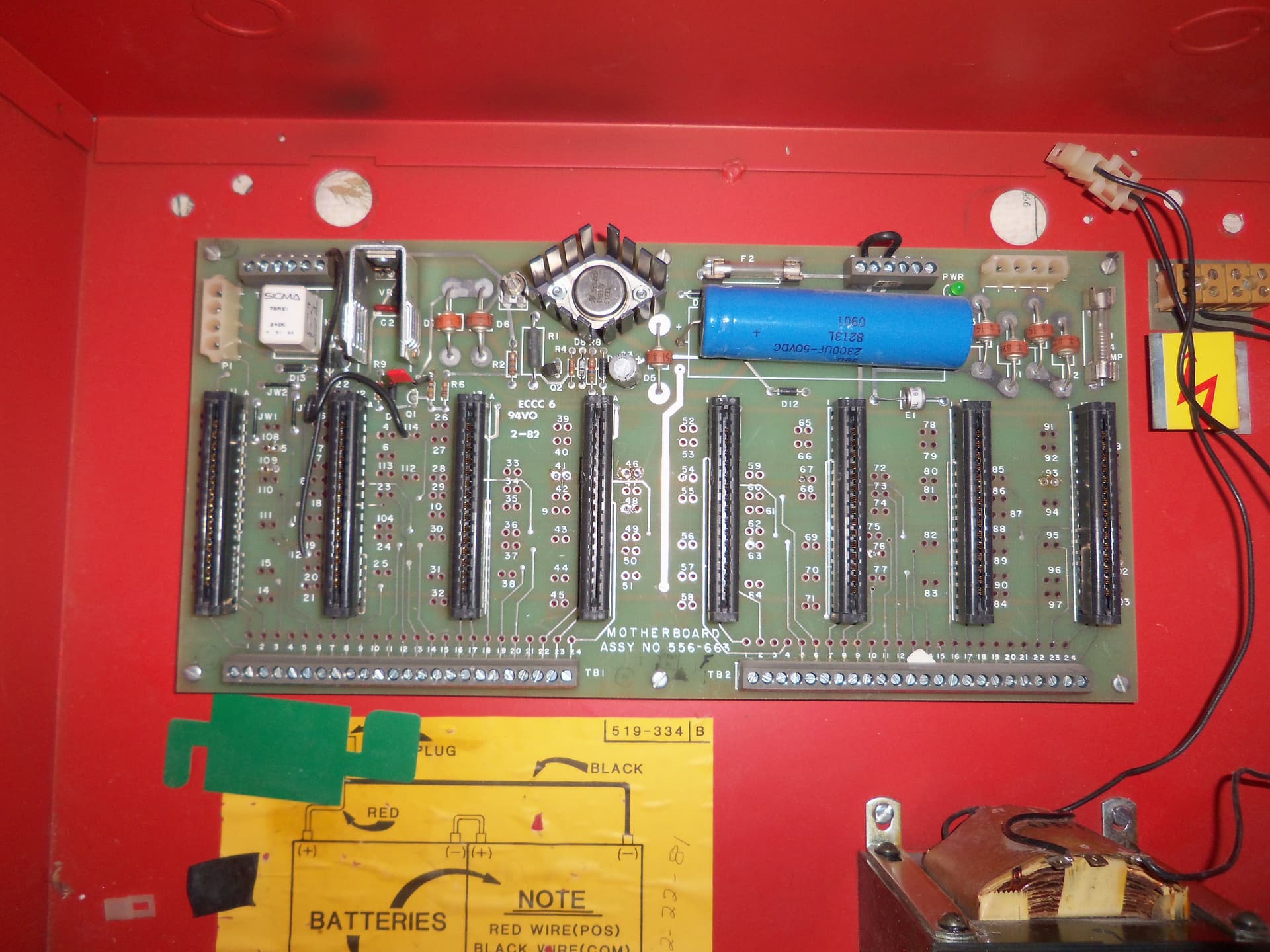
I did notice that transistor Q1 on the main motherboard is not present in my panel when I unpacked it. Every other board I’ve seen online seems to have this transistor. Q2 and Q3 are there. Do you think this missing transistor could be why I’m not getting power to the cards? It possibly could have broken off during shipping or something, unless this transistor was not in place from the factory. From the solder pads, it’s hard to tell if it was there or not originally. There are no resistors connected to any of the terminals. Here’s the thing. None of the trouble lights have ever lit up on any of the cards, nor do they go into alarm when the test switches are flipped, which implies to me that power is not getting past the main control card out to the other cards, or past the meter card, although the meter card doesn’t show any sign of current flow either. With the original control card, no lights at all ever comes on besides the main green power LED on the board. With the spare control card, only the one trouble LED on the control card itself is steadily lit, while the rest of the cards remain dark. I’ve tried moving the cards around, swapping the zone cards for the dual zone cards, etc. and none of these do anything different. I am getting good voltages to the main board, I checked some of the voltages on the terminals at the top left and I have 30 volts from terminal 1 to 5 and 1 to 6 on TB4. My theory on why the trouble LED comes on with the spare control card but not the original, is perhaps that spare card is configured differently for some reason and allows power to that LED only. All of the solder connections on the board look good, I even checked the back of the board. The card slots look clean and nothing is broken.

The part numbers of the original one zone cards are all 556-915A.
The part number of the original single signal card is 556-031E.

For right now I have the dual zone and dual signal cards in there.

Thank you for the info on that, good to know that I can swap the zone and signal cards without reconfiguring. Thanks for the info on how the two types of zone cards will land differently on the terminals, I will keep that in mind.

That helps as well, thank you. Once I get the panel working and am ready to add the marchtime card, I will cut that diode on the control card. Thanks again for the help!

They most definitely made quality equipment, especially before the Tyco and now JCI days. Their clock systems also really have my interest, specifically their digital clocks and clock panels from the 1980’s with the red LED displays. Working on trying to find one of those soon. Just love vintage electronics in general. That kind of blows that the power supply in the 4020 is no good. I’m guessing an internal ground fault? But hopefully you’ll be able to fix it, those are really fun panels to toy around with. Thank you for the kind words as well, my 3rd year is going very well.

So Q1 missing may be a problem. Could I get a close up picture of where on the board that is? I’m wondering if that is a part of the rectifier circuit. If Q1 did in fact break off, if you can figure the values you can most definitely replace it.

As far as the main control cards go, there shouldn’t be any sort of configurations that would cause them not to work. The only thing you can alter is D25. D25 would have no effect on the internal card bus receiving power to my knowledge. The only thing I could think of is that it is either an issue with that one transistor missing, or something somewhere else along the line is damaged.

This is most definitely a head-scratcher for sure. But I’m sure we can figure something out. Once I can get to storage, I’ll pull out my 2001-8023, and take a look at that to help you figure out how to wire the march-time card. It’s pretty simple, with wiring going from the main control, passing thru the march-time card and to the signal card, but I’ll have to look at my panel to get a reference as to what pins we will be using. I also have some wiring diagrams somewhere that Brad Corey (Retired STR_SG) sent me years ago for the 2001 repak. If I can find them, I’d be glad to scan them and DM them to you. But, you are most certainly welcome. I’m glad I can help someone else restore one of their panels, always makes me happy to see these old gems work again.

Yes they really did. Back when Simplex Time Recorder was still in the Watkins family. I’ve heard that it was the best company past STR employees ever worked at and I wish I had been around back then to have worked for them before Tyco and JCI. Their clock systems interest me as well, I’d love to find one of the antique wooden master clocks which will go well with a few other antiques I own, as well as a few of the electric slave clocks to hook up to one of the master time panels, such as the 2350 if I ever got my hands on one of those. I love vintage electronics in general as well, I restore them as one of my hobbies and fire alarms have always been a part of that. The LCDs, LEDs, intricacy of the circuitry, build quality, are all reasons why I love STR equipment. And I think I will be able to fix it, I don’t think there’s any ground fault, I think it just died one day which is why it was replaced. Most likely a capacitor or something went open in the power supply circuit which caused the switching oscillator not to start, is my guess. (No transformer, just uses a switching power supply) Hopefully will be a pretty straightforward fix to get it going again. They seem really fun to work with. Also you’re welcome, I’m glad that you are enjoying it and I wish you all the best :slight_smile:

It looks to me like it’s past the main rectifier, but it could still be in the power circuit. I will get a close up or two and include them in this reply. It’s a PNP transistor, I have one that should work if it indeed is the cause of the problem.

Interesting, yeah me too. I’m thinking both control cards probably work, I don’t know why one would have it’s trouble LED work in the current state the panel is in and the other not, though. Either way power doesn’t seem to be getting through to any other cards.

I’m sure we can as well, thanks for the help and time to take a look at it, that would be handy to be able to have a reference for the march time card. I’m glad Mr Corey was able to send you those wiring diagrams. He truly was a huge help with anything Simplex in this community. Thanks a lot, and I completely agree. So many of them have been lost to the scrap pile over the years and there’s not many of these 2001s left, repaks or otherwise. It makes me happy to be able to own one in the cosmetic condition that it is, and be able to preserve it for generations to come so that Simplex’s historic legacy in the fire protection industry isn’t forgotten. It’s also nice to see someone else around my age who is passionate in saving vintage electronics and keeping them working. It’s a great thing to do and a great feeling of accomplishment you get from it.

Here’s a few close ups of the board around the Q1 area and area relating to the first card slot :


1 Like

Also, on this schematic, if I’m looking at it right, I believe this is the power supply circuit and same Q1. To the left is the bridge rectifier.

1 Like

You’re absolutely right about that. I’ve even heard a story (I believe it was on the r/firealarms reddit page), but back when the company was owned by Chris Watkins, he would send employees $5 and a card on their birthday, which is wild. Not too many companies would do that, or care about their employees like that. Those 2350 master clock panels are my absolute favorite from them, mainly for two reasons. 1 - that really neat, red LED display and 2 - it shares a lot of the same design features as the 2001. Trying very hard to find one, and I may have the chance do get one soon depending on money and a few other things.

Hopefully you can fully repair the power supply on the 4020, as those things are not cheap. I wonder if the problem lies within the gold-wing power supply itself, or the interface board that sits next to it. If it’s a capacitor, I’d think it would be the interface board, but I’m not 100% on that.

So for your 2001, I would say to go ahead and replace that transistor since you have the part. To me, it seems like it snapped off the motherboard. As you pointed out before, all other 556-663 motherboards have that transistor in that spot. I’d also say it is definitely supposed to be there if it is included in the diagrams. Now as to what that controls, I have no clue as I am not the best at reading electrical schematics, you’re probably better at that than me. But I’d say to replace it, and see what that does. I’m betting that’s the issue, as I can’t think of any other reason as to why the panel would not be functioning, especially if nothing else is damaged. But if you do replace it, let me know what happens. Really hoping that does the trick.

Much agreed, too. It’s pretty cool to see someone else who is pretty much the same age as me having a passion for old electronics. It most definitely gives you a feeling of accomplishment and almost pride in a way when you fix these things. But definitely keep doing what you’re doing, there aren’t too many people our age that keep these old things ticking.

I heard that one too, was pretty cool! The Watkins family sure treated their Simplex employees like family. I think Simplex was pretty unique in the care that went into their employees. The 2350s are very neat, I love that red LED display as well. I hope you will be able to acquire one when money and whatnot permits!

I hope so too, I believe the problem will be in the power supply itself, I’ve seen other electronics that don’t have any power and the problem is always on the power supply board. The power supply itself will have filtering capacitors and bypass capacitors and whatnot which I’ve seen cause the supply not to start the oscillator it needs to operate when they go bad. Or a blown fuse, shorted regulator, etc. Can happen as well.

Okay so I replaced that transistor Q1 with a generic multi purpose PNP transistor I had (a 2N3906 part no.) and sadly the issue still persists. I made sure the transistor followed the markings on the board. I can’t believe I’d have two bad control cards. Could it have something to do with the meter module or the jumpers for it? Also, when you get a chance maybe you can give me a few of the key voltages that I should have and tell me where to check for them, so I can make sure all the voltages are where they need to be. As well as possibly measure across that Q1 transistor on one of your 2001s, and tell me what the resistance is between pins of the transistor (or voltages, if you want to do it powered up) so I can get an idea where my readings should be. I can’t imagine much else would be wrong. The second main control card I put in, the trouble LED and piezo have power but that’s as far as I’ve gotten. None of the other LEDs on the cards light up when I push LED test and no relays click when I press reset. It’s like the power isn’t getting beyond the main control card. What else interests me, is that orange capacitor that looks like it was added in, I wonder why that’s on my board.

Yes it really is, it’s very fun to work on these things and you’re absolutely right about it giving pride, it feels great! Thank you, I hope throughout your college days you will still have time here and there to work on things. It’s very fun and we need more people to keep these old things ticking and not forgotten!

1 Like

The big question is (and I should have asked earlier) was this panel functional when it was removed? If it was functional when it was removed, and it was removed recently, then I cannot imagine what in the world went wrong between then and now.

Well, here is what you could try, and of course, that is only if you are comfortable with this. You can try desoldering the jumper wires for the meter module to see if that would do anything whatsoever. It may be best to essentially remove all “options” and strip the main board down to how it would have come from the factory - with no jumper wiring for optional cards. The panel will still work, you just won’t have a functional meter card anymore.

I wish I could be more help in telling you what voltages you should be getting, but I currently don’t have a meter, I have to go buy one. I’m still going to try and help the best I can though. I can’t see the control cards being bad either, it seems to be an issue with something on that main board. The behavior you described on the second control card is very interesting, because it is very similar to the behavior of the panel when reset is pressed in. Usually, when the reset button is pressed, the main control card cuts power to the card bus in the panel (so all of the zone cards, signal cards, etc), the trouble LED illuminates and the piezo sounds. So it’s almost like its stuck in reset (hence the cards not getting power), but I can’t think of a reason as to why that would be…but if you do decide to desolder the meter module’s wires, let me know what results that yields. Also, none of the traces are damaged (either on the front or back of the main board, or control cards), right? The fact that Q1 was physically busted off makes me a little weary of more potential damage.

Come to think of it, looking at that orange component that was added on, it looks like it was done almost in place of that snapped off transistor. If you look at the traces on the board around Q1, one side goes to that resistor on the right, while the other goes to what I am assuming is a diode on the left. That orange (capacitor?) was connected to both those components, almost like it was a replacement for Q1. I’m not sure if that makes any sense at all, but that could be a possibility. So maybe remove that, and leave the jumpers for the meter in place for now. Let me know what that does.

Haha, I was following what you said and cut that mysterious orange capacitor out and while doing so it looks like I found the problem, finally!! Go back up and look at the voltage regulator transistor. I don’t know how I missed this all along, but the main voltage regulator is completely blown in half! From the angle it was at, it was shadowed by the heatsink, it looked like another component until I looked closer and noticed the regulator was missing a leg, then it hit me! That “component” was the other half of the regulator! No wonder there’s no voltage lol. I wonder if it got hit by a surge or something or someone shorted some wires while it was powered up. I might have a regulator for it. I just hope nothing else got blown out. I still wonder the whole reason for the missing Q1 and capacitor, though. You’re right in that the capacitor is essentially across Q1.

Oh, wow! That went right under my nose too! Yeah to me it seems like there was some sort of power surge that took it out, which is probably why it was removed. If you haven’t already, you might want to check those two fuses on the main board as well just to be safe. But I’m glad you may have found the problem. Let me know what happens when you get it replaced, hopefully that’s all it needs. Later on, probably later this weekend or early next week, I’ll dig out my 2001-8023 “repak” from storage, and I’ll help you get the march-time card configured. That shouldn’t take too long to do. The whole Q1 thing is still a mystery to me. Maybe someone tried repairing it before you got it, and was never successful at doing so? Would explain Q1 missing and the soldered-on capacitor…

1 Like

Mine too, I can’t believe I missed that right in front of me all this time! Haha. Yeah I think so too, the Simplex tech who very kindly sent it to me said he didn’t know the history on the panel, as it was sitting in his boss’s office and his boss and his shipping guy went ahead and sent it to me. They know I’m interested in these old Simplex products. Thank you, I did check the fuses and they are both good. Everything else looks good, and I went ahead and ordered a few 24V regulators that are the same part number as the original, as I only had 5 and 12 volt regulators on hand. I’m very thankful to have gotten such a great example of a 2001, and it will be great to see it up and running, which at that point once you have the time to do so, we will configure the march time card once that arrives as well. The Q1 thing is for me as well, now that I found the failed 24v regulator, I’m thinking possibly someone did that as a repair attempt as well, or maybe the regulator also took out the transistor or something similar? Still strange with the capacitor essentially across Q1, but I went ahead and replaced the transistor and removed the capacitor, so it’s back to factory specs at this point aside from having the meter module fitted.

It most certainly is a fantastic example of a 2001 given its condition for being around 40 years old. I don’t know how many collectors actually have a 2001, but I don’t believe there are too many out there. But nonetheless, welcome to the 2001 club. Glad you ordered some regulators, hopefully that gets it up and running. I honestly could not see anything else being wrong with it, unless components also blew on any of the cards (hopefully that isn’t the case). But once your marchtime card arrives, just let me know and I’ll try to get down to my storage unit to dig out my 2001 repak. I’ll probably have to wait until some of the snow and ice melts to get to it though, as western PA (where I am) got walloped by a winter storm last night. But I am most definitely excited to see this panel up and running. Now all you need is a 4251 series pull box, and a 2903 horn/light, and you’ll have the perfect example of a classic 1980’s Simplex system.

It really is, it’s in mint shape. For some reason it doesn’t have the metal data tag/nameplate with the model number and date on the door like most have that I’ve seen, it must have gone missing somehow. Instead it’s got a shiny Simplex sticker on it though so that makes up for it haha. I don’t think there are either, there’s not many 2001 related videos on YouTube either. Finally I can start making some haha! I don’t think any of the cards were damaged, and I got spare zone and signal cards with it as well.

Take your time if needed. I received the march time card tonight that I ordered. Still waiting on the voltage regulator to get the panel up and running, which should be here soon. I will let you know when I get the panel going, then we can work on configuring it for march time. I have a dual signal card that I would like to use, and configure the march time card to code signal circuit 1, while upon pressing ACK and silencing the signals, let signal circuit 2 slow pulse the circuit until the panel is reset.

Great news! The voltage regulator arrived today and I got it replaced and the board reinstalled, threw in some cards, and I’m happy to report that the panel is now fully functional. Troubles come on as I expected, and when I alarm a zone it goes into alarm and the signal circuits activate. All of the buttons work as expected.

Now a side note to that, it appears that all of the original cards that were in the panel when I got it with the exception of the meter card (four single zone cards, control card, and the one signal card) are also damaged. But that’s okay, since I wasn’t planning on using those anyway. I have the spare control card installed which is working great, as well as the dual zone cards and the dual signal card, which are the cards I am going to use along with the march time card which will be the next step. For now I will leave the meter card in place. Thankfully I got these extra cards with the panel. I’ve got 6 zones and 2 signal circuits.

1 Like

Fantastic! Really happy to hear that! So it seems to me like a power surge took that panel out if all of the original cards were shot as well. But I’m glad you got it working! I will try my best to help you out as soon as I can with that march-time card, hopefully tomorrow if I get some time.

Thank you, I am so happy to have a perfectly working 2001 in such great shape, it’s a beautiful panel! I agree, a surge most likely did it in. But I’m glad I was able to give it new life again. Thank you, I’d love to get the march-time card configured. Do you know off hand what EOL resistor values I need for the zones and signals? I also have an annunciator trouble on the main control card.

Here is the panel in it’s fully working state with the cards I have installed. Slot 6 is where the march time card will be added. I may or may not swap one of the zone cards for slot 7 just to switch things up. I have one blank for any slot that isn’t used.